
More Information
Submitted: 10 December 2019 | Approved: 30 December 2019 | Published: 31 December 2019
How to cite this article: Gaud B, Singh A, Jaybhaye S, Narayan H. Synthesis of Carbon Nano Fiber from Organic Waste and Activation of its Surface Area. Int J Phys Res Appl. 2019; 2: 056-059.
DOI: 10.29328/journal.ijpra.1001017
Copyright License: © 2019 Gaud B, et al. This is an open access article distributed under the Creative Commons Attribution License, which permits unrestricted use, distribution, and reproduction in any medium, provided the original work is properly cited.

Synthesis of Carbon Nano Fiber from Organic Waste and Activation of its Surface Area
Brijesh Gaud1, Amrita Singh1, Sandesh Jaybhaye1 and Himanshu Narayan2*
1Nanotech Research Lab, Department of Chemistry, B.K. Birla College, Kalyan 421 304, India
2Department of Physics & Electronics, National University of Lesotho, Roma 180, Lesotho
*Address for Correspondence: Himanshu Narayan, Professor of Physics, Department of Physics & Electronics, National University of Lesotho, Roma 180, Lesotho, Tel: +266 5221 3521; Email: [email protected]; [email protected]
Carbon Nano fibers (CNFs) have recently attracted a lot of attention due to their widespread range of technological applications attributed to their unique physical and chemical properties, such as, small size, high strength, high adsorption linked with their large specific surface area, high temperature tolerance and corrosion resistance. CNFs have been used in energy conversion and storage, reinforcement of composites and self-sensing devices. The complete removal of entrapped metallic impurities and amorphous carbon incorporated with CNFs has been a long-standing issue. We have developed a new approach for preparing graphitic CNFs and its activation of surface area by purification. This approach entails Thermal Decomposition (TD) based synthesis of CNFs from organic solid waste, such as, stems of rice plants. CNFs are synthesized from organic waste precursor (Rice Stems) at 900 oC under inert atmosphere. The active surface area was measured using a Surface Area Analyzer. Morphology of CNFs was studied with using SEM and XRD. The SEM image shows that the synthesized CNFs have diameter ranging within 45-60 nm.
Properties of porous carbon and carbon based nano-materials strongly depend upon the methods of synthesis employed. Carbon materials have attracted much attention due to their wide range of physical and chemical properties, which lead to broad range of utilities in advanced engineering materials, such as, in aerospace, transportation, actuators, sensors, fuel-cells, radar-absorbing materials, wind-turbine blades, electromagnetic interference shielding, and expensive sporting goods. They also find applications in catalysis, electronic devices, gas and liquid separation, and memory storage devices [1-3].
Carbon fibers and nano fibers are the carbonic materials with high porosity and high specific surface area [1]. Carbon Nano Fibers (CNFs) have unique tubular structures with their diameter in nanometer range, and effectively have large specific surface area [4]. The basic shape of CNFs is cylinderical, with varying lengths and diameters. CNFs have superior physical and chemical properties, and very high mechanical strength. These unique properties make them suitable for a number of applications, e.g., as sensors and probes, thermal resistance, energy storage, and in many other optical, electronic and medical applications [4].
Vapor-grown CNFs have attracted much interest because they have the potential to provide solutions to many problems in composite applications. Unlike glass fibers, they are electrically conducting and therefore suitable for applications that require the ability to discharge electrostatic potentials, provide sufficient conductivity for electrostatic painting, or even shielding from radio frequency interference or lightning strikes. Moreover, their thermal conductivity is excellent [5,6].
In recent years, nanoparticles have been drawing attention [7] in the composite industry sector as they have the ability of enhancing the mechanical and physical properties of fiber-reinforced composites synthesized through older methods. Their nanometer size, connecting to high specific surface area, combined with extraordinary mechanical, electrical and thermal properties, make CNFs unique nano-fillers for structural and multifunctional composites. While there is so much investigation reporting wide range of utilities of carbon nanotubes and CNFs in composites, the potential of these nano-materials to enhance the damping properties of composites still remains relatively less explored [8-10].
Numerous research works for the synthesis of Carbon Nano Materials (CNMs) have been carried out using precursors obtained from fossil fuel and petroleum products. The availability of such precursor and its cost are factors that determine the cost-effectivity of finally produced carbon nanomaterials. Hence, there is a need to search for new sources of precursors, which are not fossil-fuel based. Plant derived precursors can yield CNMs of similar, and sometime even better, quality than one would normally get starting with fossil-fuel materials and petroleum [11].
In the present work, we synthesized the CNFs using Stems of Rice plants by the method of Thermal Decomposition (TD). Stems of Rice plants are usually dumped and incinerated by the farmers, which leads to a number of environmental issues. Transformation of such biomass to emerging renewable materials is advantageous compared to the traditional dumping and incineration [9].
Among the various resources available for synthesis of nanostructured materials, plant waste is superior in terms of cost-effectiveness and it is eco-friendly also. Hence, we tried to synthesize the CNFs using plant based biomass through the TD route. The active surface area analysis has been done using Surface Area Analyzer instrument before and after the treatment with 50% Conc. HCl and HNO3. Morphology of CNFs was investigated through Scanning Electron Microscopy (SEM), Atomic Force Microscopy (AFM) and X-Ray Diffraction (XRD) analyses.
CNFs were synthesized from organic waste precursor, i.e., stems of the rice plant collected from Kalyan, India. The stems of the rice plant were washed with distilled water to remove surface contamination (e.g., dust, pesticide, etc.). It was then soaked in 10% KOH solution for 12 h. The soaked samples were washed with distilled water several times to reach the neutral pH and dried in oven at 120 oC. Finally, the dried stems of rice plant were thermally decomposed at 900 oC under inert atmosphere of hydrogen gas for 2 h in a horizontal furnace. The CNFs were treated with 50% Conc. HCl and HNO3 to remove the alkali, amorphous carbon and metals present. Finally, the CNFs were filtered and washed with distilled water several times to reach the neutral pH, and finally dried in an oven at 100 oC.
Characterization techniques
FT-IR Spectroscopy: The CNFs was mixed with potassium bromide (KBr) (FTIR grade) in the ratio of 1:2 and pressed with the help of hydro-press to make pellets. The sample pellet was positioned into the sample holder and FTIR spectra were recorded on FTIR-4100 (Jasco).
Scanning Electron Microscopy (SEM) and Energy-Dispersive X-Ray Spectroscopy (SEM-EDX): SEM was done at IIT Bombay, India on a Jeol JSM -7600F FEG-SEM Model No. JSM-7600F with SEI Resolution 1.0 nm at 15 kV, 1.5 nm at 1 kV, in GB mode having magnification as low as 25X to 10,000X to as high as 100X to 1,000,000X with accelerating voltage ranging from 0.1 to 30 kV and probe current ranging from 1 pA to ≥ 200 nA [3].
X-Ray Diffraction (XRD) analysis: XRD measurements were accomplished at IR-Tech Lab, Mumbai, India on MiniFlex machine unit with Cu-Kα radiation (λ = 1.54178 Å) at 40 kV and 15 mA, at a scan-speed of 04.00 º/min.
Raman spectroscopy: Raman spectroscopy is based on the Raman Effect, which results from interactions of the vibrational modes of molecules with electromagnetic radiation. Raman spectroscopy is well known as a powerful tool for the characterization of carbon structures. The ratio of intensities of the D and G bands, R, gives interesting information on the structure of carbon materials [3]. It was carried out at University of Mumbai, India.
Surface area analysis: Active surface area was analyzed through BET Surface Area Analyzer from Smart Instruments Co. PVT. LTD.
In this work we developed easy, reliable and eco-friendly methods for synthesis CNFs. The waste Stems of the rice plant were pyrolysed at 900oC in an inert atmosphere to get CNFs.
FTIR Spectroscopy
FT-IR analysis (Figure 1) show that synthesized treated CNFs have C–C and C=C stretching which was indicated by peaks at 1595 cm-1 and 1397 cm-1, 705 cm-1, 917cm-1, 993 cm-1 also indicate the C–C binding stretching in finger print region and peak at 3431 cm-1 indicate that presence of amine (NH2) group on the smooth surface of CNFs [8].
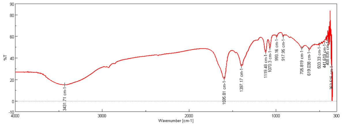
Figure 1: FT-IR Spectra of CNFs purified with 50% Conc. HCl and HNO3.
Surface morphology: SEM analysis (Figure 2a,b) shows that the average diameter of the CNFs is 40-60 nm and they have smooth surface. Figure 2a shows matrix residue on CNFs Surface, which was removed by treatment with acid as shown in figure 2bc. The EDAX spectra in figure 2d shows the absence of other impurities like metal salts, such as, halides and oxides.
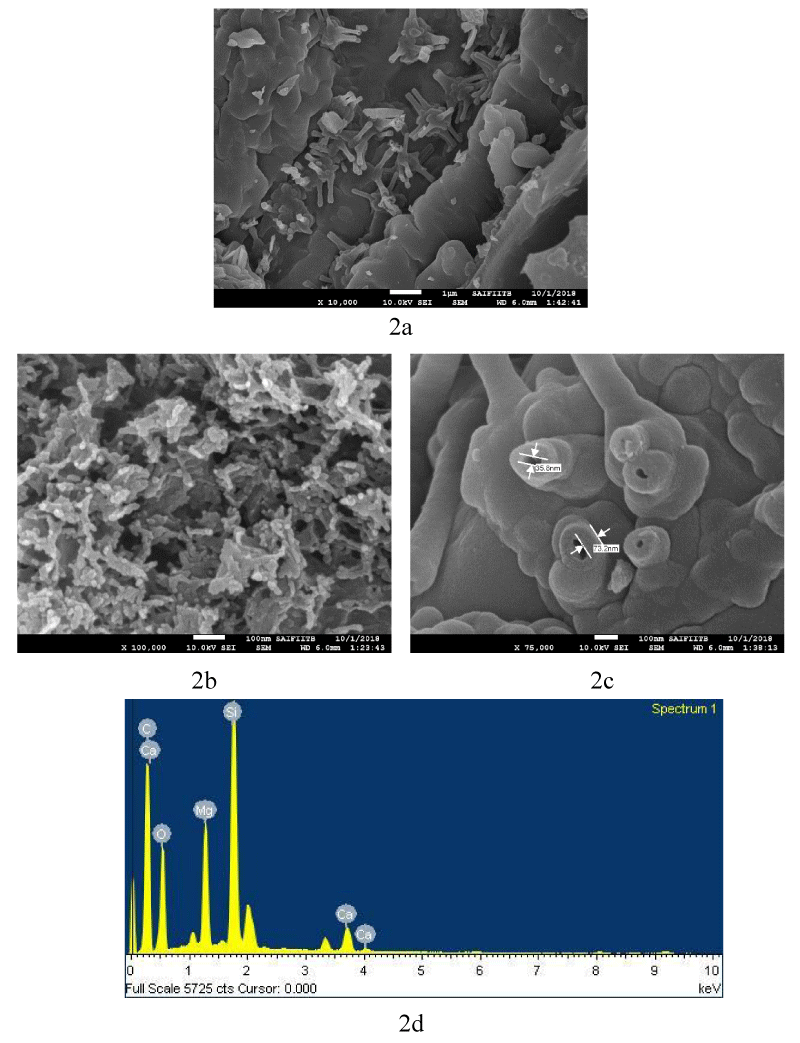
Figure 2: SEM image of 2a) As Grown CNFs; 2b) and 2c) Shape and size of CNFs purified with 50% Conc. HCl and HNO3; 2d) SEM EDAX spectra of CNFs.
Figure 2a further shows the presence of CNFs of a few micrometer in length. Figure 2b depicts a closer view of the same CNFs showing length in the range of a few hundreds of nm or longer. Figure 2c demonstrates a clear picture of one of the CNFs, showing aperture of around 35.8 nm size for a fiber, and the wall measuring around 73.2 nm in another one.
X-Ray diffraction analysis: The X-Ray Diffraction (XRD) pattern for as synthesized CNFs (Figure 3a) show broadening of spectra as compared to the one shown in figure 3b for purified CNFs sample. This indicates the presence of impurities in as synthesized CNFs. Figure 3b further shows a sharp peak at 26.46° corresponding to carbon crystallographic structure of the carbon fibers. The sharp peaks at 26.46°, 42.35°, 44.41° and 54.49° for Hexagonal shape (JCPDS No. 00-008- 0415) marked by their indices [0 2 2], [1 0 0 ], [1 0 1 ], [1 0 4 ] were also observed. The diameter of the CNFs calculated from Scherrer formula was found to be around 33 nm.
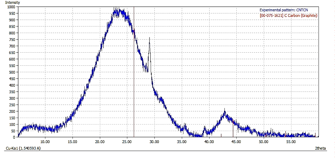
Figure 3a: XRD Spectra of Synthesised CNFs.
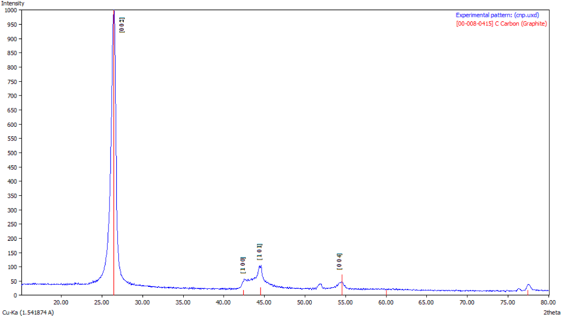
Figure 3b: XRD Spectra of Purified CNFs with 50% Conc. HCl and HNO3 acids.
Raman spectroscopy: The ratio of the intensities of disorder-induced phonon mode (D-band) and graphite band (G-band) in Raman spectra is a good indicator of the quality of samples. Figure 4 shows the intensities of these Raman bands that indicate a high quantity of structural defects present in the samples [9].
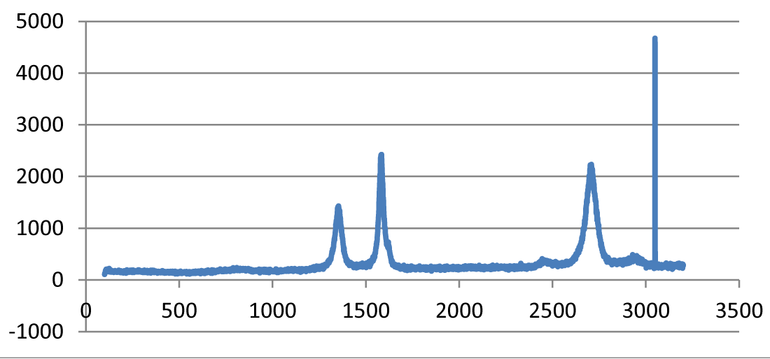
Figure 4: Raman Spectra of treated CNFs.
The G-band is visible at 1550–1600 cm−1, which is produced from the high degree of symmetry and order in carbon materials. The D-band at 1250–1450 cm−1 is related to the disorder-induced phonon mode at the boundaries of Brillouin zone. The second order D-band (also called the D∗-band), which is related to the boundary point K in Brillouin zone of graphite and depends upon the packing in three-dimensional space, is evident around 2500–2900 cm−1. Moreover, the peaks at 2785 cm−1 and 3111 cm−1 are due to symmetric and asymmetrical C–H stretching vibrations of the CH3 group, and asymmetrical C–H stretch vibrations of the CH2 group, respectively. The band at 1600 cm–1 is assigned to the conjugate C=C bond, and the band around 1388 cm–1 is due to the CH2 twisting.
Atomic Force Microscopy (AFM) analysis: The size and shape of the CNFs were obtained directly from tip-corrected AFM measurements, and the shape of the CNFs is estimated on the basis of AFM images and line scans. Figure 5 show the tube like structure of CNFs with average diameter (inner and outer wall) of 149.4 nm.
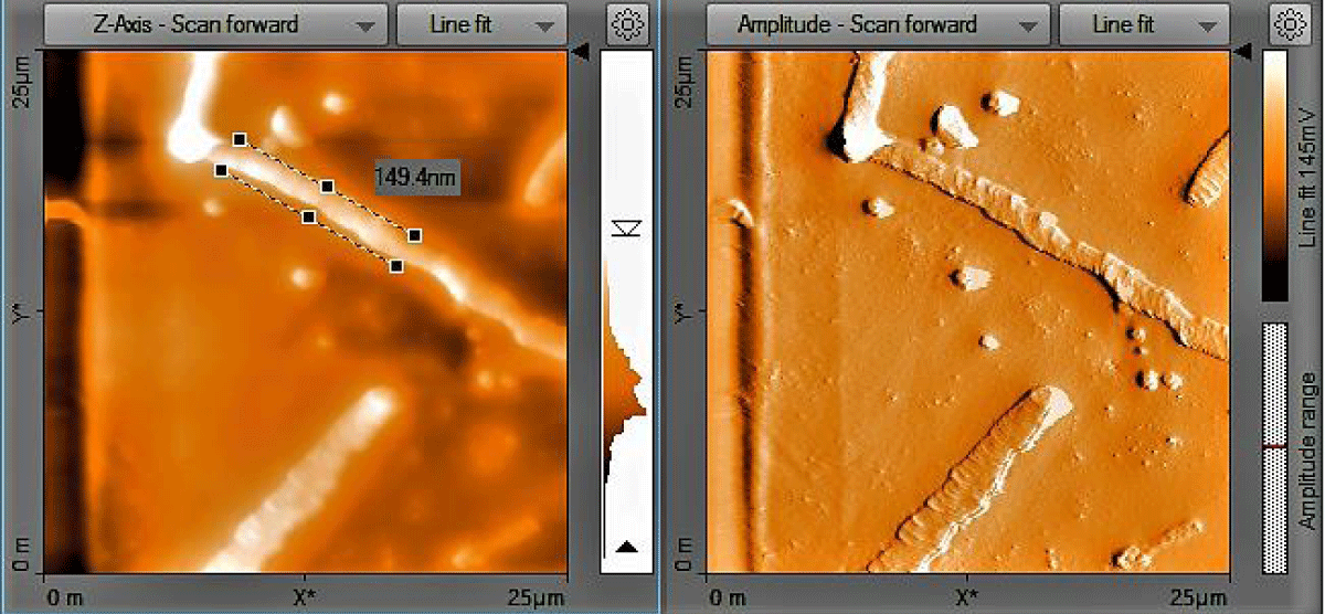
Figure 5: AFM Image of treated CNFs.
Surface area analysis: Surface area of as synthesized CNFs was found to be 106 m2/g which increase on treatment with 50% Con. HCl and HNO3 to be 250 m2/g.
Effect of acid treatment
Acid treatment is one of important ways to improve the graphitization of CNFs and remove the amorphous carbon. The effects of acid treatment on synthesized CNFs were shown by the increased surface area and the quality of the synthesized CNFs. The surface area of synthesized CNFs from rice stem was about 106 m2 g and acid treated CNFs have 250 m2/g. Clearly the specific surface area was found to increase after acid treatment, which may be attributed to more efficient graphitization of the fibers.
Qualitative CNFs can be synthesized from organic waste precursors, i.e., stems of rice plant. The average diameters of the CNFs synthesized in this investigation were found to be in the range of 40-60 nm. The treatment of CNFs with 50% Conc. HCl and HNO3 shows that matrix residue on the surface of CNFs was completely removed, and a smooth fiber surface was obtained. Acid treatments not only removes the amorphous carbon but also it improved the active surface area. Such CNFs may find applications in the areas of sports, automotive, construction industries, aerospace, marine, and electrical energy sectors etc.
The authors would like to acknowledge the Director, Dr. Naresh Chandra, and Principal Dr. Avinash Patil of B.K. Birla College, Kalyan, India for their support and guidance. We would also like to thank the I.R. Technology Services Ltd., Ghansoli, Navi Mumbai, India for their support in material analysis.
- Soutis C. Fiber reinforced composites in aircraft construction. Prog Aerospace Sci. 2005; 41: 143–151.
- Paiva JMF, dos SantosII ADN, Rezende MC. Mechanical and morphological characterizations of carbon fiber fabric reinforced epoxy composites used in aeronautical field. Mater. Res. 2009; 12: 367–374.
- Mallick PK. Fiber reinforced composites: material, manufacturing and design. 3rd Ed. 2008; New York: CRC Press.
- Bigdeli S, Fatemi S. Fast nanofiber carbon growth on the surface of activated carbon by microwave irradiation: A modified nano-adsorbent for deep desulfurization of liquid fuels. Chem Eng J. 2015; 269: 306–315.
- Alimohammadi F, Gashti MP, Shamei A, A novel method for coating of carbon nanotube on cellulose fiber using 1, 2, 3, 4-butanetetracarboxylic acid as a cross-linking agent. Prog Org Coatings. 2012; 74: 470–478.
- Tibbetts G, Lake ML, Strong KL, Rice BP. A review of the fabrication and properties of vapour-grown carbon nanofiber/polymer composites. Comp Sci Technol. 2007; 67: 1709–1718.
- Narayan H, Alemu H, Alotsi DN, Macheli L, Thakurdesai M, et al. Fast and complete degradation of Congo red under visible light with Er3+ and Nd3+ ions doped TiO2 nano composites. Nanotechnology Development. 2012; 2: 5–11.
- Tibbetts GG. Why are carbon filaments tubular? J Cryst Growth. 1984; 66; 632–638.
- Gou J, O'Braint S, Gu H, Song G. Damping augmentation of nanocomposites using carbon nanofiber paper. J Nanomater. 2006; 1–7.
- Jaybhaye S. Carbon nanostructures synthesized from bitter almond seeds and their hydrogen adsorption capacity. SMC Bull. 2012; 3: 19-22.
- Shearon M, Shearon M. Carbon Nanomaterials and their Synthesis from Plant‐Derived Precursors: Synthesis and Reactivity in Inorganic, Metal-Organic, and Nano-Metal Chemistry. Thematic Rev Nanosci. 2006; 36.
- Nizamuddin S, Siddiqui MTH, Mubarak NM, Baloch HA, Mazari SA, et al. Advanced Nanomaterials Synthesis from Pyrolysis and Hydrothermal Carbonization: A Review. Current Org Chem. 2018; 22: 446–461.
- Singh A, Gaud B, Narayan H, Kurkure R. Eco-Friendly Synthesis of Zinc Oxide Nanoparticles for Rayon Pulp. Proc NULISTICE. 2018; 76–80.
- Osswald S, Havel M, Gogotsi Y. Monitoring oxidation of multiwalled carbon nanotubes by Raman spectroscopy. J Raman Spectrosc. 2007; 38: 728–736.
- Liu Y, Pan C, Wang J. Raman spectra of carbon nanotubes and nanofibers prepared by ethanol flames. J Mater Sci. 2004; 39: 1091–1094.