
More Information
Submitted: 29 April 2020 | Approved: 28 July 2020 | Published: 31 July 2020
How to cite this article: Adar E, Yosher AM, Baranov SA. Natural ferromagnetic resonance in cast microwires and its application to the safety control of infrastructures. Int J Phys Res Appl. 2020; 3: 118-122.
DOI: 10.29328/journal.ijpra.1001028
Copyright License: © 2020 Adar E, et al. This is an open access article distributed under the Creative Commons Attribution License, which peRmits unrestricted use, distribution, and reproduction in any medium, provided the original work is properly cited.
Keywords: Cast glass-coated amorphous magnetic microwire; Magnetostriction; Natural ferromagnetic resonance; Distant safety control

Natural ferromagnetic resonance in cast microwires and its application to the safety control of infrastructures
E Adar1, AM Yosher1 and Serghei Alexei Baranov2*
1Wire Machine Technologies Ltd (WMT), 30600 Or Akiva, Israel
2Institute of Applied Physics, Academy of Sciences of Moldova, MD 2028 Kishinev, Moldova
*Address for Correspondence: Serghei Alexei Baranov, Institute of Applied Physics, Academy of Sciences of Moldova, MD 2028 Kishinev, Moldova, Email: [email protected]; [email protected]; [email protected]
The natural ferromagnetic resonance (NFMR) in cast glass-coated amorphous magnetic microwires has been studied theoretically and experimentally. The NFMR reveals large residual stresses appearing in the microwire core in the course of casting. These stresses, together with the magnetostriction, deteRmine the magnetoelastic anisotropy. Beside the residual internal stresses, the NFMR frequency is influenced by external stresses applied to the microwire or to the composite containing the latter (the so-called stress effect).
The dependence of the NFMR frequency on the deformation of the microwires is proposed to be used in the distant diagnostics of dangerous deformations of critical infrastructure objects such as bridges, dams, wind turbine towers, skyscrapers, stack-furnaces, embankments, etc. To this end, fragments of magnetic microwires will be embedded in the bulk of concrete structures or fixed on their surface during construction or after it by means of coating with a special concrete-adhesive plaster. Further, these structures are periodically irradiated with microwaves from a radar at frequencies close to the original NFMR, and the presence of latent dangerous deformations of the concrete structure is judged by the NFMR frequency shift.
Interest in magnetic microwires has greatly increased in the last few years mainly due to their technological applications. Especially glass-coated amorphous magnetic micro- and nanowires (GCAMNWs) are nowadays attracting much attention because of their applicability for multifunctional radio absorbing shielding.
The glass-coated microwires were first introduced in 1924 by Taylor [1]. They consist of an inner metallic nucleus (core, kernel) covered by a Pyrex-like coating (shell). The cast GCAMNWs are manufactured by means of a modified Taylor-Ulitovsky process [2-4]. The preparation of microwires and studies of the magnetic properties were reported in many publications by various Research groups [2-19].
For Fe-rich GCAMNWs with positive magnetostriction, the easy magnetization direction lies along the wire axis, as deteRmined by the maximal component of the stress tensor, that is, axial tensile stress [4,6-8]. The microwires exhibit a unique domain structure characterised by axial domains.
The phenomenon of natural ferromagnetic resonance (NFMR) in CGCMMWs [4,6-13] is extremely interesting from the viewpoint of using it for non-contact diagnostics of distant objects. The diagnostics become possible due to the stress effect on the NFMR, that is, the shift of the resonance frequency as a result of a deformation of the object (and, consequently, of the magnetic microwires mechanically connected to the latter). Such a frequency shift can be measured by irradiating the object with microwaves emitted by a radar at frequencies near the NFMR and detecting the reflected signal, thus revealing a deviation of the resonance frequency from the original value.
The remote testing proposed by us in the present article will allow the monitoring of dangerous deformations of critical infrastructures, such as bridges, dams, wind turbine towers, high-rise buildings and stack-furnaces of theRmal power plants, embankments, etc., which are threatened with physical damage during natural or technological disasters, especially repeated ones. It is well known that a large peRcentage of the destruction and resulting victims of earthquakes occur during repeated aftershocks of the earth’s crust which are weaker than the primary tremors. However, no information on the implementation of such a control method has been published, although recent Research in the field of NFRm in microwires has become more intense [4,6-13,19].
To assess the feasibility of implementing the described method of monitoring of the infrastructure facilities’ safety (as well as for other applications), we examine the correlation between the NFMR frequency ranging from (1…12) GHz (deteRmined by the dispersion of the permeability when a microwave passes through a controlled object with embedded magnetic microwires), and mechanical stress of the microwire cores (for example, during stretching and/or bending). The correlation between the mentioned frequency and the alloy composition in the microwire core (or magnetostriction in the range from (1…40) ppm) was also checked.
Theoretical studies performed simultaneously have shown that a significant peRcentage of absorption can be attributed to the geometric resonance effect, while the effect of the composition is expected for thin microwires when the kernel radius is comparable with the thickness of the skin layer.
The main peculiarity of GCAMNWs is that they consist of an amorphous magnetic alloy kernel (a metallic conductor) with a diameter between (0.1…50) μm, covered by a Pyrex-like coating with a thickness of (0.5…20) μm. During the aforementioned fabrication process, the metallic kernel solidifies together with the glass coating. Therefore, strong residual stresses originated by rapid quenching from the melt itself, as well as by the quite different theRmal expansion coefficients of the metallic alloy and the glass coating, take place. These residual stresses strongly affect the magnetic properties and even the crystallization process of glass-coated microwires. More technological aspects of the Taylor-Ulitovsky method for the production of cast GCAMNWs, which can have various microstructures and compositions of the metallic core, are presented in [2-4,10,11].
Theoretical aspects of the distribution of residual stresses
The glass coating of the cast GCAMNWs protects the metallic kernel from corrosion and provides electrical isolation. Besides, it induces strong mechanical stresses in the kernel. The theory of residual stress is presented in [4]. The mechanical stresses in the kernel deteRmine the magnetoelastic anisotropy which is at the origin of a unique magnetic behavior.
In cylindrical coordinates, the residual tension is characterized by the axial, σz, radial, σr, and tangential, σφ, components which are independent of the radial coordinate. The value of these stresses depends on the ratio of the radius, Rm, of the metallic kernel to the total microwire radius, Rc:
(1)
Using the cylinder-shell model, we then obtain a formula for stresses in the metallic kernel of the cast GCAMNWs:
(2)
(3)
where εE1 = σ0 ~ 2 GPa is the maximum stress in the metallic kernel; ε is the difference between the theRmal expansion of the metallic kernel and that of the glass shell with the expansion coefficients α1 and α2: ε = (α1 – α2)(T* – T); E1 is the Young modulus of the metallic kernel, T* is the solidification temperature of the composite in the metal/glass contact region (T* ~ (800…1000) K), T is the room temperature. The technological parameter k is the ratio between Young's moduli of the glass and the metal: k = E2/E1 ~ 0.3…0.6, ν is the Poisson ratio. Let us consider the case where all the Poisson ratios are ν = 1/3 in order to obtain
, (4)
. (5)
The general theory of residual tension is presented in Ref. [4], where other calculations of residual tension are criticized. Here we will analyze the case where the depth of the skin layer is smaller than the core radius r. In this case, Equations 1-5, provide a good description of the experiment.
For materials with positive magnetostriction, the orientation of the microwire magnetization is parallel to the maximal component of the stress tensor, which is directed along the axis of the microwire. Therefore, cast Fe-based microwires with a positive magnetostriction show a rectangular hysteresis loop with a single large Barkhausen jump between two stable magnetization states and exhibit the phenomenon of NFMR. Equations (1-5) adequately explain the experiments concerning FMR and NFMR.
We suggested a model in which the residual stresses σr and σz in the GCAMNW monotonically decrease towards the strand axis. This model differs from the models of the standard theory [5].
With additional longitudinal strain, which occurs when the microwire is embedded in a solid matrix that itself deforms under external influence, the following teRm is added to the expression for the residual axial tension:
(6)
where Po is the foRce applied to the composite; Sm is the microwire cross-sectional area; k is the ratio of the Young modulus of the shell to that of the microwire; x is the ratio of the cross-sectional area of the shell to that of the microwire.
Mutifunctional shielding using fe68c4b16si10mn2 microwires
The theory of NFMR is presented in [6-8]. A cast GCAMNW was considered to be a ferromagnetic cylinder with a small radius Rm. We introduce the depth of the skin layer, δ:
δ ~ [ω(µµ0)eff Σ2]‒1/2 ~ δ0(µ)1‒1/2 (7)
where (µµ0)eff is the effective magnetic permeability, and Σ2 is the electrical conductivity of the microwire. In the case of our magnetic microwires, with the relative permeability µ ~ 103 (see below) and ω ~ (9…10) GHz, δ varies from (1…2) μm.
It is known [6-13] that for Rm > δ the general expression for the FMR frequency, ω, is:
(ω/γ)² = (Hk + 4πMs)·Hk (8)
where Ms is the saturation magnetization, and
γ ~ 3 МHz/Oe is the gyromagnetic ratio. The anisotropy field is given by Hk ~ 3λσ/Ms, where λ is the magnetostriction constant, and σ denotes the mechanical stress originated during the fabrication procedure (Equations 1-6).
The NFMR frequency can be written as
(9)
where
Near the NFMR frequency, the dispersion of the permeability, μ, is given by
μ(ω) = μ’(ω) + iμ’’(ω) (10)
with μ’’ exhibiting a peak and μ’ passing through zero at resonance [4,6-8].
Figure 1 shows the resonance frequency of 9.5 GHz for a Fe68C4B16Si10Mn2
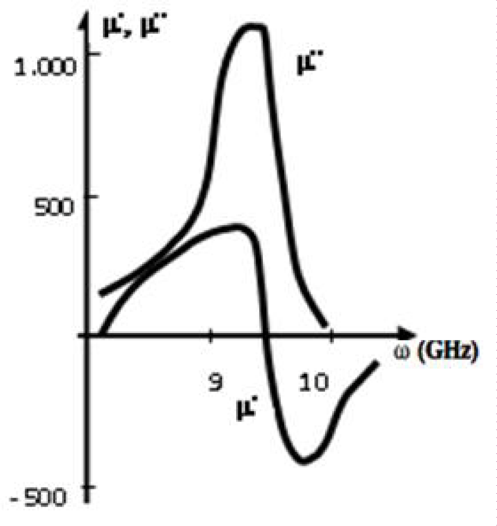
Figure 1: Frequency dispersion of the real and imaginary parts of the relative permeability around the NFMR frequency for the Fe68C4B16Si10Mn2 microwire (Rm ~ 5 μm, x ~ 5).
In the vicinity of the resonance μ’’ is described by [6-8]:
μ’’/μdc ~ ГΩ/[(Ω – ω)² + Г²] (11)
where μdc is the static magnetic permeability, and Г is the width of the resonant curve. Very close to the resonance, Г > (Ω – ω), Equation (11) reduces to μ’’/μdc ~ Ω/Г ~ 103.
Modulating the diameter of the microwire and the magnetostriction through its composition enables one to fabricate microwires with a tailorable permeability dispersion for radio-absorption applications [6-8]:
Determining the resonant frequency in the range from (9…12) GHz;
Controlling the maximum of the imaginary part of magnetic permeability.
Pieces of microwires have been embedded in planar polymeric matrices to form composite shielding for radio-absorption protection. Experiments were performed employing commeRsub>cial polymeric rubber with a thickness of (1…3) mm. Microwires were spatially randomly distributed within the matrix prior to its solidification. The concentration was maintained below (8…10) g of microwire dipoles ((1…3) mm long) per 100 g of rubber [4,6-8].
A typical result obtained in an anechoic chamber is shown in figure 2 for radio-absorbing shielding with embedded Fe68C4B16Si10Mn2 microwires. As observed, an absorption level of at least 10 dB is obtained in a frequency range of (8…12) GHz with a maximum attenuation peak of 30 dB at about 10 GHz. In general, optimal absorption is obtained for microwires with metallic kernels of diameter 2Rm ~ 10 μm (x ~ 5) and length L = (1…2) mm. These microwire pieces can be treated as dipoles whose length L is comparable to the half value of the effective wavelengths Λeff/2 of the absorbed field in the composite material (i.e., in connection to a geometric resonance). A similar result has been received for radio-absorbing shielding with a different GCAMNW [4,6-8].
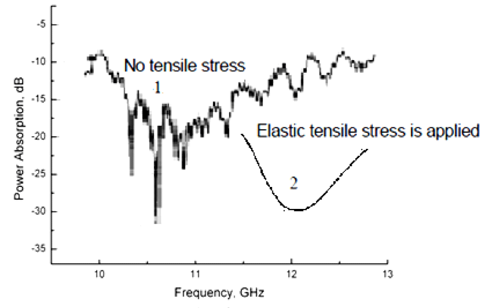
Figure 2: 1 – Average absorption characteristics of a shielding containing a microwire composite exhibiting NFMR at microwave frequencies ranging from (10…12) GHz for Fe68C4B16Si10Mn2 microwires (Rm ~ 5 μm, x ~ 5). 2 – Hypothetical absorption curve in case of an external pressure.).
It is possible to explain experimental results using the theory presented in [6-8,20,21]. Although the design of the absorption shielding can be based on disposing the dipolar pieces in a stochastic way, we consider, for simplicity, a theoretical analysis for a diffraction grating with a spacing between wires of Q < Λ (Λ is the wavelength of the absorbed field). The propagation of an electromagnetic wave through an absorbing shielding with microwire-based elements is characterized by transmittance, |T|, and reflectance, |Rr|, coefficients given by
|T| = (α2 + β2)/[(1 + α)2 + β2] (12)
|Rr|= 1/[(1 + α)2 + β2], (13)
where α = 2Xr/Z0, β = 2Y/Z0 with Z0 = 120π/Q, and the complex impedance Z = Xr + iY.
The absorption function G, is correlated with the generalized high-frequency complex conductivity Σ, (or high-frequency impedance, Z). Here we use the analogy between the case of a conductor in a waveguide and that of a diffraction grating. The absorption function, given by
|G| = 1 ‒ |T|2 ‒ |Rr|2 = 2α/[(1 + α)2 + β2] (14)
has a maximum of |Gm| = 0.5 |G| for simultaneously α = 1 and β = 0, for which |T|2 = |Rr|2 = 0.25. The minimum |G| = 0 occurs at α = 0.
Theoretical estimations, taking into account only the active resistance of microwires, result in an attenuation within a range from (5…15) dB being much lower than the experimental results, which, for a spacing of microwires of Q = 10-2 m, range between 18 and 15 dB, while for a spacing of Q = 10-3 m it increases up to (20…40) dB. Thus, it becomes clear that the shielding exhibits anomalously high absorption factors, which cannot be explained solely by the resistive properties of microwires.
The high-frequency conductivity, Σm, of a stochastic mixture of microwires in a polymeric matrix can be expressed as a function of conductivities, Σi, of non-conducting (polymeric matrix) and conducting metallic kernel GCAMNW elements, Σ1 and Σ2, respectively:
Σm = B + (B2 + AΣ1Σ2)½ (15)
where B = 1/2·[Σ1(X2 ‒ AX1) + Σ2(X2 ‒ AX1)], and Xi is the fractional volume: (X1 + X2) = 1; A = 1/(J1 ‒ 1) with J1 ~ (J + Y/Xr) being the fractal dimension of the system (J is the geometrical dimension of the system) and Y/Xr ~ (Rm/δ)2 [8,20].
Let us consider the effective absorption function (as in Equation (14)):
|Geff| ~ ГeffΩeff/[(Ωeff – Ω)² + Гeff²], (16)
where Гeff ≥ Г and Ω ~ Ωeff = 2πc/Λ.
A microwave antenna will resonate when its length L, satisfies the condition
L ~ Λ/[2(μeff)½]. (17)
The NFMR in a single Fe68C4B16Si10Mn2 microwire (see Figure 1) occurs at Ωeff ~ 9.5 GHz, and the absorption curve in figure 2 froFe68C4B16Si10Mn2 microwire pieces exhibits a maximum at Ωeff ~ 10 GHz (Λ ~ 3 cm) and μeff ~ 103 (according to Figure 1).
This corresponds to
L ~ 1…3 mm, (18)
where the concentration of microwires (X2 < 0.2 according Equation (15)) is well below the perclation threshold. A higher concentration of dipoles increases both the absorption, |Geeff|, and the reflectance, |Rr1|, which can be simply evaluated [1,8,20]:
|Rr1| ~1 ‒ 2√[Ω/(2πΣm)] (19)
where Ω/2π ~ 1010 Hz. Equation (19) is applicable if the reflection factor, |Rr1|, is small. (We consider Σm ~1011 Hz).
One of the important technological features of the GCAMNWs is the high rate of cooling and solidification of the composite fibers drawn from the molten alloy and consisting of a ferromagnetic metal core and a glass coating. Significant differences between the theRmal expansion coefficients of the glass and metal alloy lead to the appearance of large residual stresses.
Particular attention has been paid to the parameters deteRmining the anisotropy of cast GCAMNWs. The continuous casting of GCAMNWs (Taylor-Ulitovsky method) has some limitations, deteRmined by the physical properties of metal and glass [4].
We have presented simple analytical expressions for the residual stresses in the metallic kernel of the microwire, which clearly show their dependence on the ratio of the external radius of the microwire to the radius of the metal kernel and on the ratio of Young’s modules of glass and metal. Our modeling, based on the theory of theRmoelastic relaxation, shows that the residual stresses increase from the axis of the microwire to the surface of its metallic kernel, which is in accordance with the previously obtained experimental data [4]. Thus, in the manufacture of cast microwires with a glass coating by the Taylor-Ulitovsky method, the residual stresses reach maximum values on the surface of the metal core [6-8].
The cast GCAMNWs exhibit natural ferromagnetic resonance (NFMR), whose frequency depends on the composition, geometrical parameters and deformation of the microwire. The NFMR phenomenon observed in glass-coated magnetic microwires opens up the possibility of developing new radio-absorbing materials with a wide range of properties. An important feature of cast microwires with an amorphous magnetic core is the dependence of the NFMR frequency on the deformation (stress effect). In this regard, the microwave response of a composite consisting of segments of amorphous magnetic microwires with a glass coating in a flat dielectric plate is investigated when the plate is deformed in a microwave field with a frequency in the range from(1...10) GHz. As shown by calculations (Equations 8,9), the shift of the NFMR frequency as a result of the stress effect can reach 20% before the destruction of the composite. Therefore, this effect can be used for contactless diagnostics of deformations in distant objects (including critical infrastructures) reinfoRced by cast magnetic microwires with the stress effect of NFMR. To this end, these objects are periodically scanned with a floating-frequency radar to deteRmine the deviation of the initial NFMR frequency due to potentially dangerous deformations of the monitored object.
It is worth mentioning also another principle of detecting mechanical strain which is examined in [22]. This principle is based on the giant magnetoimpedance (GMI) effect (Figure 3), so that it is different from that presented in figure 2. The GMI effect demands external magnetization of the sample which is not required in the NFMR method [6-8]).
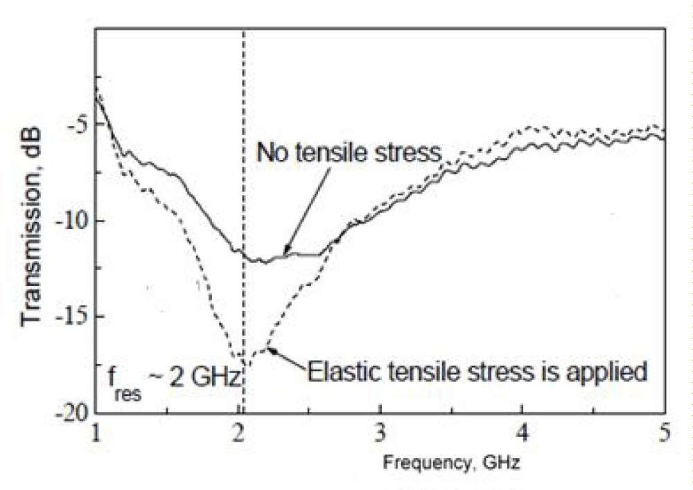
Figure 3: Stress dependence of the transmission coefficient for a single-layer composite sample measured in the free-space near field [22].
- Taylor GF. A metod of drawing metallic filaments and a discussion of their properties and users. Phys Rev. 1924; 23: 655-660.
- Vázquez M. Soft magnetic wires, Physica B: Condensed Matter. 2001; 299: 302-313.
- Vazquez M, Zhukov AP. Magnetic properties of glass-coated amorphous and nanocrystalline microwires. J Magn Magn Mat. 1996; 160: 223-228.
- Baranov SA, Larin VS, ToRcunov AV. Technology, preparation and properties of the cast glass-coated magnetic microwires. Crystals. 2017; 136: 1-12.
- Antonov AS, Borisov VT, Borisov OV, Prokoshin AF, Usov NA. Residual quenching stresses in glass-coated amorphous ferromagnetic microwires. J Phys D Appl Phys. 2000; 33: 1161-1168.
- Baranov SA. Use of a microconductor with natural ferromagnetic resonance for radio-absorbing materials Tech. Phys. Lett. 24, 1998, 549-550.
- Baranov SA, Yamaguchi M, GaRcia KL, Vazquez M. Dimensional absorption high-frequency properties of the cast glass coated microwires. Surf Engin Appl Electrochem. 2008; 44: 425 -427.
- Baranov SA. Engineering microwave properties of microwires. Moldavian J Phys Sci. 2015; 14: 201-214.
- Marín P, Cortina D, Hernando A. High-frequency behavior of amorphous microwires and its applications. J Magn Magn Mater. 2005; 290–291, 2005, 1597-1600.
- Peng HX, Qin F, Phan MH. in Ferromagnetic microwires composites: from sensors to microwave applications. Springer. Switzerland 2016; 12-14.
- Qin F, Peng HX. Ferromagnetic microwires enabled multifunctional composite materials. Progr Mater Sci. 2013; 58: 183-259.
- Kraus L, Infante G, Frait Z, Vázquez M. Ferromagnetic resonance in microwires and nanowires. Phys Rev B. 2011; 83: 1-11.
- Kraus L. Theory of ferromagnetic resonances in thin wires. Czech J Phys. 1982; 32: 1264-1282.
- Reynet O, Adenot AL, Deprot S, Acher O, Latrach M. Effect of the magnetic properties of the inclusions on the high-frequency dielectric response of diluted composites. Phys Rev B. 2002; 66: 1-9.
- Starostenko SN, Rozanov KN, Osipov AV. Microwave properties of composites with glass coated amorphous magnetic microwires. J Magn Magn Mater. 2006; 298: 56-64.
- Yıldız F, Rameev BZ, Tarapov SI, Tagirov LR, Aktaş B. High-frequency magnetoresonance absorption in amorphous magnetic microwires. J Magn Magn Mater. 2002; 247: 222-229.
- Ménard D, Britel M, Ciureanu P, Yelon A. Giant magnetoimpedance in a cylindrical magnetic conductor. J Appl Phys. 1998; 84: 2805-2814.
- Ménard D, Yelon A. Theory of longitudinal magnetoimpedance in wires. J Appl Phys. 2000; 88: 379-393.
- Nematov MG, Adam AM, Panina LV, Yudanov NA, Dzhumazoda A, et al. Magnetic anisotropy and stress-magnetoimpedance (S-MI) in current-annealed Corich glass-coated microwires with positive magnetostriction. J Magn Magn Mater. 2019; 474: 296-312.
- Baranov SA. Generalized conductivity and optimum energy release. Tech Phys. 1999; 44: 853-854.
- Born M, Wolf E. In Principles of Optics: Electromagnetic Theory of Propagation. Interference and Diffraction of Light, Pergamon Press, Oxford. 1970; 30.
- Makhnovskiy D, Zhukov A, Zhukova V, Gonzalez J. Tunable and self-sensing microwave composite materials incorporating ferromagnetic microwires. Adv Sci Technol. 2008; 54: 201-210.