
More Information
Submitted: May 05, 2021 | Approved: May 21, 2021 | Published: May 24, 2021
How to cite this article: Dong C, Sun Y. Working process of steam turbine and establishment of start-up model. Int J Phys Res Appl. 2021; 4: 039-047.
DOI: 10.29328/journal.ijpra.1001040
Copyright License: © 2021 Dong C, et al. This is an open access article distributed under the Creative Commons Attribution License, which peRmits unrestricted use, distribution, and reproduction in any medium, provided the original work is properly cited.
Keywords: 300 MW steam turbine; Start-up process; Finite element; Stress

Working process of steam turbine and establishment of start-up model
Chao Dong and Yongjian Sun*
West Road of Nan Xinzhuang, Jinan 250022, Shandong, China
*Address for Correspondence: Yongjian Sun, No. 336, West Road of Nan Xinzhuang, Jinan 250022, Shandong, China, Email: [email protected]
In the research of steam turbine rotor, start-up optimization is a very key research problem. A series of start-up optimization research can greatly improve the start-up efficiency of steam turbine and the safety performance of the unit. The start-up optimization of steam turbine is inseparable from the analysis of the start-up process of steam turbine and the mathematical model of the startup process of steam turbine unit, because the optimization of steam turbine unit can be regarded as a function to find the optimal solution. This paper analyzes the start-up process of 300 MW steam turbine, analyzes the start-up process of steam turbine unit through the data used in the actual power plant, and gives the mathematical model of cold start-up of steam turbine according to the start-up process of steam turbine, so as to further study the start-up optimization of steam turbine. Finally, the optimization model is determined by several key parameters, which are three weight coefficients α1,α2,α3, the actual damage value Di and damage limit value Dlim, and the start-up time ti and total start-up time t0 of each stage.
Turbine rotor is an important part of the unit, which carries the energy and torque of the unit. The safety of steam turbine unit mainly depends on the quality of rotor [1]. The start-up model of steam turbine unit is the key factor to optimize the start-up of steam turbine. To ensure that the stress value of steam turbine rotor is less than the yield limit value of rotor material is the decisive factor to shorten the start-up time of steam turbine unit. From a few years ago to now, people’s quality of life has been significantly improved, the power grid capacity has also been significantly improved, so the peak value of the power grid is also increasing [2]. Frequent peak shaving operation refers to frequent startup and shutdown of steam turbine units. The change of turbine working condition will cause the damage of rotor material and reduce the life of the rotor. Change the parameters of turbine greatly during the start-up process. Among them, the change of temperature parameter is the most important. Temperature changes will make the rotor produce a force, called thermal stress. At the same time, the metal material will deform, which is mainly manifested as expansion deformation. Once the thermal stress exceeds the yield limit of the rotor material, the high-temperature parts of the rotor will be damaged to some extent, which will eventually bring some potential safety hazards [3].
The needs of today’s society need to be met, so it is very necessary and important to study the quick start process. The start and stop of steam turbine depends on how long it can be used, which directly affects the service life of the unit. The start-up and shut-down of steam turbine unit are studied in detail, and the start-up and shut-down curve of the unit is given, which is used to guide the start-up and shut-down of the unit and improve the safety and economy of the unit. In a word, the start-up optimization of steam turbine is a function optimization problem. At the same time, the function has constraints. Generally speaking, the starting time is the shortest and the stress is in a reasonable range. This paper analyzes the start-up mathematical model of steam turbine through the start-up and stop process of steam turbine [4].
In the actual power plant, it is unrealistic to measure and test the input data, so using complex simulation software is the most commonly used evaluation method.
There should be a certain degree of superheat when the main steam of steam turbine enters. The superheat degree should be at least 50 oC and generally not more than 426 oC. The temperature difference between two pipes is generally less than or equal to 17 oC. The temperature difference between main hot steam and reheat steam is generally 28 oC, and the maximum temperature difference should be less than 80 oC. After the impulse start parameters are selected, before the impulse start of the steam turbine, it is necessary to conduct a comprehensive inspection on the main equipment and various auxiliary equipment, and all the equipment should have the start-up conditions. When the main equipment and other auxiliary equipment meet the start-up conditions, start the impulse start of the steam turbine. The impulse starting of steam turbine is mainly divided into four links. The first link is the impulse starting of steam turbine to 600 r/min. cut off the inlet steam quickly and conduct five minutes of friction inspection. Professional technicians listen to the internal sound of steam turbine carefully and continue to increase the speed under the condition that there is no friction in the flow passage and the oil return of bearing is normal. The standard of speed increase is generally 100 r/min. The second link of steam turbine impulse starting is warm-up. The warm-up time and speed standard should be in accordance with the start-up curve provided by the steam turbine factory. The third link of steam turbine impulse starting is that before the speed rises to the critical speed of rotor, it is necessary to check and warm up the turbine at medium speed. The fourth link of steam turbine impulse starting is that when the steam turbine is warming up at medium speed, the time and temperature of warming up should meet the requirements provided by the manufacturer when the steam turbine leaves the factory. After the impulse start of the steam turbine is completed, the professional technicians should measure and record all relevant data. After recording the data, they should conduct a comprehensive inspection on the operation status and various components of the steam turbine. After checking that there is no problem, they can carry out relevant tests. When the speed is reset again in the test, they should rise to the constant speed again at 200 r/min.
The safe and trouble free start-up of the unit, especially the turbine rotor, is often an important factor to limit the load change rate of the unit or to improve the acceleration during the start-up process. Janusz, et al. Proposed that there is no contradiction between turbine start-up optimization and economic improvement [5]. Rusin, et al. Monitored the thermal stress of the main components after heating by measuring the arm temperature, and put forward the matters needing attention [6,7] for the efficiency and life of the steam turbine unit. This paper mainly studies the boiler maximum load components, that is, pipe fittings and interface area. Through the research results, the optimal characteristics of steam temperature and main steam pressure are further demonstrated, so as to promote the rapid start-up of the boiler. But because the experiment is only carried out in the selected designated area, and the experiment assumes that the heat load of the system is uniform, the result error is large. The drastic temperature change of steam turbine rotor in a short period of time will lead to the increase of temperature gradient, resulting in greater thermal stress. Many scholars have studied the optimization of heating rate. Taler, et al. proposed a new optimization method, which considers thermal stress in the start-up optimization of boiler turbine system [8]. Green’s function and Pontryagin maximum principle are used. But in the analysis process of this paper, the author mainly for a certain area of the rotor, through the simplified thermal calculation and analysis, determined the thermal stress of the rotor. Although this method speeds up the measurement speed, it has strong limitations. Turbine rotor is a very complex structure, this method is more suitable for simple geometry.
Ji, et al. proposed a method to optimize the starting process by monitoring several points with high rotor stress level [9]. In this paper, a start-up plan based on multiple temperature rise rates is proposed, and the relationship between steam temperature and maximum stress is determined by regression model. PSO algorithm is used to deal with the problem of cold start optimization to find the best temperature rise rate. In this paper, the temperature rise rate is taken as the parameter and the temperature rise rate is converted into time to calculate the total starting time, which increases the calculation amount. Therefore, this paper directly analyzes the temperature rise time of the stage when analyzing the problem, eliminating the conversion process of temperature rise rate and time. Du, et al. A nonlinear model predictive control rotor is proposed. The rotor is equivalent to a cylinder with external heat transfer and optimized by shortening the start-up time [10] is proposed and its effectiveness is proved.
In the above research work, any work assumes that the initial temperature is horizontal, which is a conventional assumption, because there is no temperature data when the turbine is shut down, and the process is very long. The rotor of steam turbine is the most important bearing part of steam turbine, so the measuring device cannot be installed. Due to the different initial state of cold start, the initial temperature field of turbine rotor is also different. Different initial thermal states will affect the initial stress field. The reference [11] discusses the optimal inlet temperature of the cycle gas turbine. In this paper, the state of medium and high pressure rotor during cold start of steam turbine is analyzed. The whole analysis step is one minute to calculate the stress in order to capture the transient characteristics during start-up. In fact, the finite element analysis of steam turbine is based on the rotor model of steam turbine. The working process of steam turbine unit is analyzed, including start-up process, shutdown process and grid connection process. Finally, the mathematical model of cold start-up process of steam turbine unit is given.
The material of the turbine rotor is 30Cr1Mo1V steel (Table 1). Physical properties and chemical composition of materials are shown in table 2 and table 4. When the finite element software is used for analysis, the physical properties of 30Cr1Mo1V steel change with temperature [19], as shown in table 3.
| Table 1: The 30Cr1Mo1V steel chemical composition 1. | ||||||||||
| Element | C | Fe | CR | Cr | Si | Mn | P | S | V | Ni |
| Wt / % | 0.28 | 1.10 | 0.28 | 0.73 | 1.13 | 0.023 | 0.22 | 0.005 | 0.24 | 0.4 |
| Table 2: The 30Cr1Mo1V steel chemical composition 2. | ||||
| Temperature | Yield strength σs | Ultimate strength σb | Elongation δ | Reduction of area ψ |
| 20 oC | 629 Mpa | 779 Mpa | 20% | 60% |
| 540 oC | 465 Mpa | 520 Mpa | 29.6% | 88.5% |
| Table 3: The physical property of 30Cr1Mo1V steel. | |||||||
| Temperature | 20 oC | 100 oC | 200 oC | 300 oC | 400 oC | 500 oC | 600 oC |
| Young modulus E | 214 Gpa | 212 Gpa | 205 Gpa | 199 Gpa | 190 Gpa | 178 Gpa | 178 Gpa |
| Poisson ratio µ | 0.288 | 0.292 | 0.287 | 0.299 | 0.294 | 0.305 | 0.305 |
| Thermal conductivity λs | 48.5 W/m·K | 47.1 W/m·K | 44.8 W/m·K | 42.8 W/m·K | 40.3 W/m·K | 37.5 W/m·K | 35.3 W/m·K |
| Linear expansion coefficient αl | 0 | 11.99 | 12.81 | 13.25 | 13.66 | 13.92 | 14.15 |
| Specific heat c | 554 J/Kg | 574 J/Kg | 599 J/Kg | 624 J/Kg | 666 J/Kg | 720 J/Kg | 804 J/Kg |
| Table 4: Allowable deviation of steam parameters under rated conditions. | ||
| Parameter | Limit value | |
| Average pressure in cycle | 1.00 p0 | |
| Pressure to allow continuous operation | 1.05 p0 | |
| Main steam pressure | Deviation value allowed by unexpected situation | 1.20 p0 |
| Cold reheat steam pressure | 1.25 p1 | |
| Average temperature in cycle | 1.00 t | |
| Temperature allowed for continuous operation | t+8 oC | |
| Main steam temperature | Allowable deviation in case of accident | t+(8 14) oC |
| Allowable deviation in case of accident within 80 h | t+(14 28) oC | |
| Value not allowed | t+28 oC | |
Start-up process of steam turbine
The working process of the steam turbine is a very complex process. The simplified picture of the steam turbine system is shown in figure 1. The most important is the start-up process and shutdown process of the steam turbine. Many researches are carried out on the basis of the start-up and shutdown process of the steam turbine. There are many start-up forms in the start-up process of steam turbine. According to the air intake mode of cylinder, it can be divided into high pressure cylinder starting and medium pressure cylinder starting. According to the metal temperature of steam turbine before impulse start, it can be divided into cold start, warm start, hot start and extremely hot start [12]. In this paper, the cold start of steam turbine is used, and the cold start process of steam turbine is analyzed and studied in detail. There are many ways to stop the steam turbine. There are two ways to stop the steam turbine normally, which are compound variable pressure shutdown and sliding parameter shutdown. Combined with the working process of the steam turbine, the mathematical model of the start-up process of the steam turbine is established, and the mathematical model is analyzed in the following work [13].
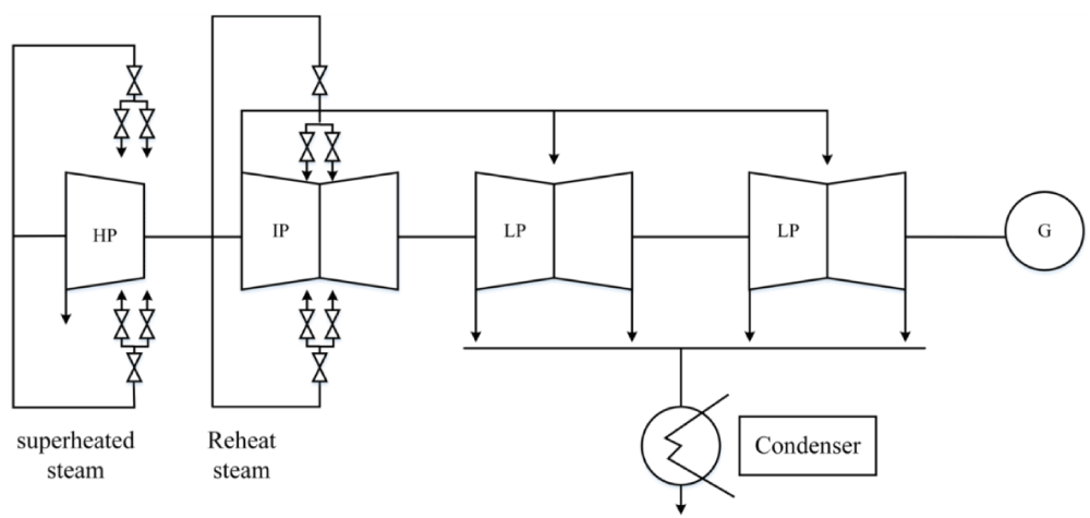
Figure 1: Simplified system picture of steam turbine.
Cold start-up and grid connection process of steam turbine
The first step in cold start-up of steam turbine is to select the impulse parameters of steam turbine [14]. When the steam turbine starts in cold state, the main hot steam pressure and reheat steam pressure and temperature in front of the main steam valve shall meet the requirements of the start-up curve provided by the steam turbine when it leaves the factory. The start curve of 300 MW steam turbine used in this paper is shown in figure 2. The cold start curve includes the temperature data, speed data, back pressure data and power data of each stage in the whole start process.
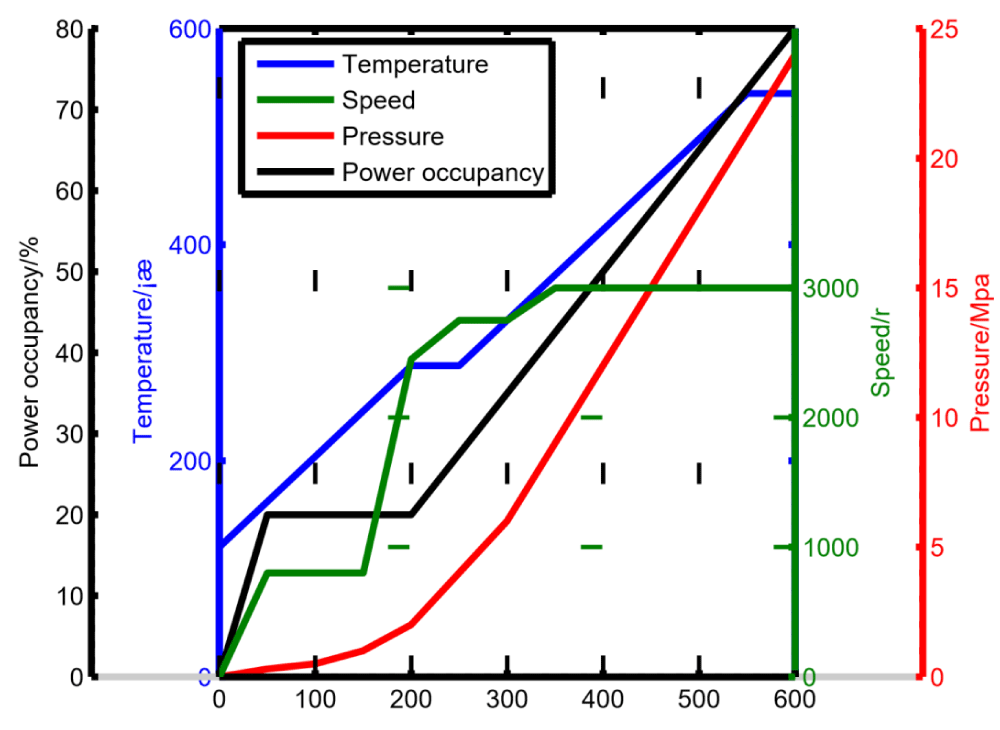
Figure 2: Cold start-up curve of steam turbine rotor.
There should be a certain degree of superheat when the main steam of steam turbine enters. The superheat degree should be at least 50oC and generally not more than 426 oC. The temperature difference between two pipes is generally less than or equal to 17 oC. The temperature difference between main hot steam and reheat steam is generally 28 oC, and the maximum temperature difference should be less than 80 oC. After the impulse start parameters are selected, before the impulse start of the steam turbine, it is necessary to conduct a comprehensive inspection on the main equipment and various auxiliary equipment, and all the equipment should have the start-up conditions. When the main equipment and other auxiliary equipment meet the start-up conditions, start the impulse start of the steam turbine [15]. The impulse starting of steam turbine is mainly divided into four links. The first link is the impulse starting of steam turbine to 600 r/min. cut off the inlet steam quickly and conduct five minutes of friction inspection. Professional technicians listen to the internal sound of steam turbine carefully and continue to increase the speed under the condition that there is no friction in the flow passage and the oil return of bearing is normal. The standard of speed increase is generally 100 r/min. The second link of steam turbine impulse starting is warm-up. The warm-up time and speed standard should be in accordance with the start-up curve provided by the steam turbine factory. The third link of steam turbine impulse starting is that before the speed rises to the critical speed of rotor, it is necessary to check and warm up the turbine at medium speed [16]. The fourth link of steam turbine impulse starting is that when the steam turbine is warming up at medium speed, the time and temperature of warming up should meet the requirements provided by the manufacturer when the steam turbine leaves the factory. After the impulse start of the steam turbine is completed, the professional technicians should measure and record all relevant data. After recording the data, they should conduct a comprehensive inspection on the operation status and various components of the steam turbine. After checking that there is no problem, they can carry out relevant tests. When the speed is reset again in the test, they should rise to the constant speed again at 200 r/min.
The allowable deviation of steam parameters during steam turbine startup is shown in table 4.
The steam turbine needs to be connected to the grid and loaded after impulse starting. The requirements for connection to the grid and loading are as follows. First of all, 5% of the rated load should be taken immediately after the turbine is connected to the grid. The 5% of the rated load is used to warm up the turbine. Under 5% load, it should run for no less than 30 minutes. During the warm-up period, the warm-up time should be increased by 1 minute for every
2 oC change of steam temperature. During grid connection and loading, the rising rate of load and the change rate of main hot steam and reheat steam must be strictly controlled according to the requirements of start-up curve. When the load rises to the predetermined load point, confirm that the corresponding valve is closed. During the warm-up process, check the vibration, oil temperature and other parameters of various parts to see if they are within the normal range. After the turbine is connected to the grid, the load should be increased as soon as possible to make it reach the load point corresponding to the start-up curve, and the temperature of the cylinder should be confirmed not to change, so as to reduce the cooling of the cylinder and rotor of the turbine. During the adjustment, the temperature difference shall not exceed the limit. The load adjustment should also adopt certain rules. Generally, the load adjustment of steam turbine will adopt the method of ”fixed sliding fixed”, that is, the method of ”fixed parameters sliding parameters fixed parameters”. In constant pressure operation, the load change rate should be determined according to the bearing capacity and adaptability of the boiler, generally 2% - 3% of the rated load per minute.
Under normal conditions, the conventional shutdown modes of steam turbine include compound variable pressure shutdown and sliding parameter shutdown [17]. The process of turbine shutdown is the reverse process of turbine start-up. In principle, the basic requirements in the startup process are applicable to shut down. However, the cooling rate shall be less than the temperature rise rate during the startup of the turbine. Generally, the temperature reduction rate shall be controlled at 1 oC - 1.5 oC, and the reasonable selection shall be made according to the purpose of shutdown and the characteristics of the shutdown process. The shutdown mode of the turbine and the target value of cooling of the cylinder and rotor. When selecting the sliding parameter shutdown mode, the superheat of the main hot steam and reheat steam of the steam turbine should be greater than or equal to 50 oC. During the normal shutdown of the steam turbine, the vacuum should be maintained until the speed is reduced to 400r/min. The protection of steam turbine is also a very important link. In order to ensure the safety of steam turbine in use during the period of shutdown or standby, effective anti-rust measures must be taken to make thermal equipment and key components corroded and damaged [18].
Stress generation process of steam turbine
The main components of the turbine rotor are the main shaft and impeller, and the turbine rotor is the most critical component in the turbine unit. At present, with the development of steam turbine towards large capacity boiler, the steam turbine rotor is becoming larger and larger, including the volume and weight of the steam turbine rotor. High temperature and high pressure steam blows to the blades of the steam turbine rotor, so that the rotating torque is transmitted to the main shaft through the blades. The high temperature steam passes through the long main shaft from the first stage to the last stage, so the temperature will drop, which leads to the uneven temperature distribution on the rotor. At the same time, due to the slow heat conduction on the rotor surface and inside the steam turbine, there will be uneven temperature distribution, which will cause the thermal stress of the main shaft. The thermal stress of the rotor is mainly calculated by the finite element analysis software, and the thermal stress curves of four monitoring points are calculated, as shown in figure 3.
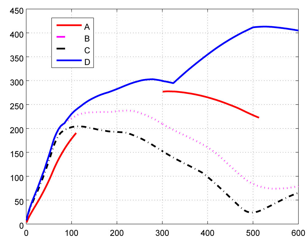
Figure 3: Thermal stress curve of steam turbine rotor.
There are many kinds of stresses in steam turbine rotor, including not only thermal stress, but also centrifugal stress and vibration stress, among which the most important are thermal stress and centrifugal stress. Because the values of thermal stress and centrifugal stress are relatively large, and other stress values are very small, the thermal stress and centrifugal stress can be mainly analyzed in the analysis and research, and other stresses can be ignored. The thermal stress is caused by the difference of temperature distribution of steam turbine due to rotor the uneven heating of rotor, while the centrifugal stress is caused by the rotation of rotor. The centrifugal stress is different from the thermal stress. The thermal stress will gradually decrease when the warm-up time keeps the same with the temperature, and then increase again when the temperature rises again. And the centrifugal stress increases with the increase of the speed, and when the speed is constant, the centrifugal stress will also maintain a relatively stable level with the constant speed of the steam turbine, and will not decrease with the constant speed. The rotor of steam turbine rotates at high speed in the process of start-up and operation. After rotation, it will produce a centrifugal force of its own, which will produce tangential stress on the rotor. By analyzing the centrifugal stress of the rotor of start-up and operation, further analyze how to select the monitoring surface and its characteristic parameters under the characteristics of its own structure. The damage suffered by the rotor is low cycle fatigue damage. The energy intensity theory, which is the fourth strength criterion, is a special formula for calculating the stress and damage value of steam turbine rotor material. The calculation formula of centrifugal stress is shown in eq.1.
(1)
where, σt represents the centrifugal stress, σe is the value of centrifugal tangential stress at the rated speed, N is the speed in the formula, and Ne is the rated speed. It can be seen from the formula that the calculation of centrifugal stress is mainly related to the speed of steam turbine rotor and the centrifugal tangential stress at rated speed. The speed of steam turbine during cold start is reflected in the curve of cold start. The speed data can be extracted to analyze and calculate the centrifugal stress of rotor. The change rule of turbine speed during cold start is shown in figure 4.
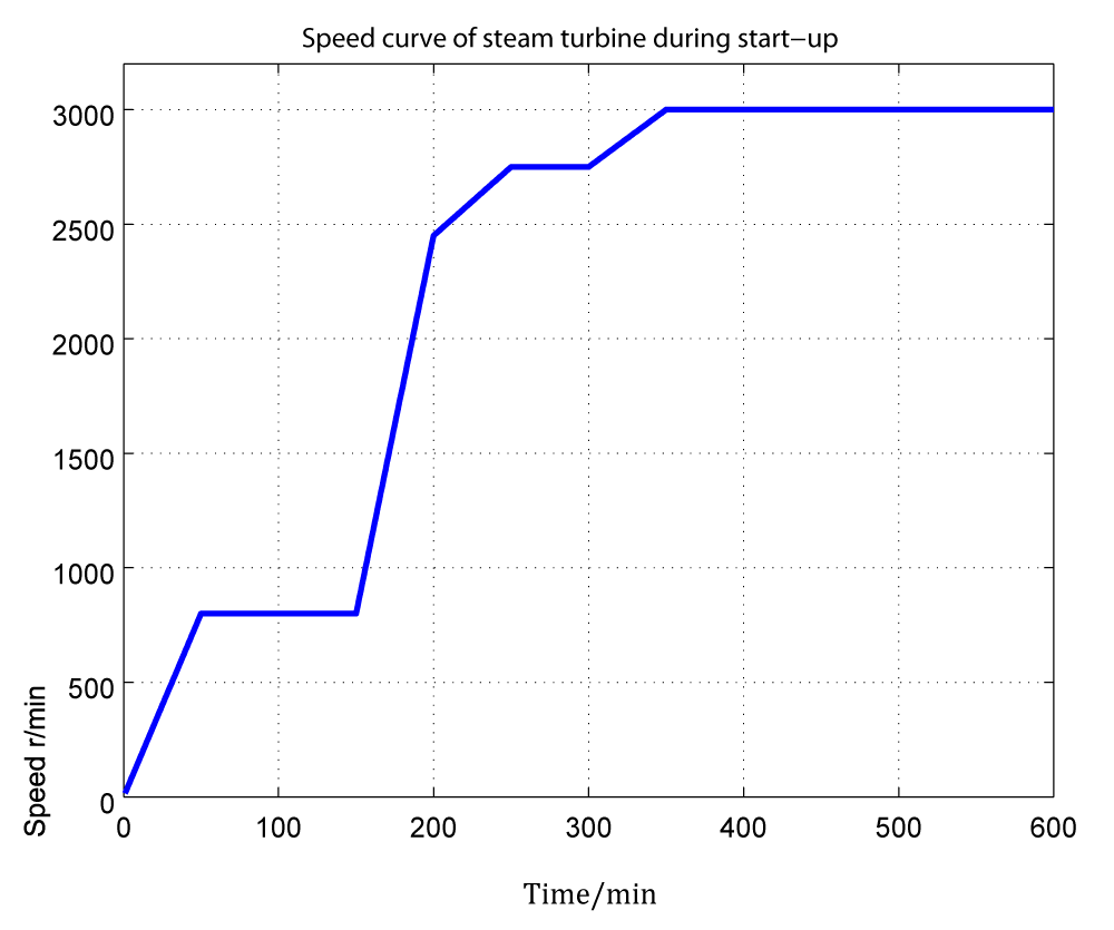
Figure 4: Speed curve of steam turbine during start-up.
According to the above speed curve of the rotor, the centrifugal stress of the rotor can be calculated through the fourth strength criterion, because as shown in eq.2, the centrifugal stress of the rotor is mainly related to the real-time speed of the turbine and the centrifugal tangential stress under the rated speed of the rotor. The centrifugal stress calculated is shown in figure 5.
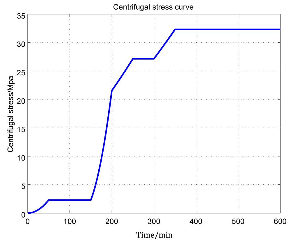
Figure 5: Centrifugal stress curve.
The correlation between the centrifugal stress of the rotor and the speed of the turbine is very high, mainly because the centrifugal stress of the rotor is positively correlated with the real-time speed of the turbine rotor. The effective stress of steam turbine is the superposition of thermal stress and centrifugal stress of steam turbine rotor, but the superposition here is not simply the summation of thermal stress and centrifugal stress, but calculated by the fourth strength criterion formula. The centrifugal stress of the steam turbine rotor is directly related to the real-time speed. The centrifugal stress and the speed of the steam turbine are actually a problem of one-dimensional equation. With the increase of the rotor speed, the centrifugal stress increases. When the speed reaches the rated speed of 3000 r/min, the speed of the steam turbine will be constant, and then the centrifugal stress of the steam turbine will be constant.
It can be seen from the above figure that the correlation between the centrifugal stress of the rotor and the speed of the steam turbine is very high, mainly because the centrifugal stress of the steam turbine rotor is positively correlated with the real-time speed of the steam turbine rotor. The effective stress of steam turbine is the superposition of thermal stress and centrifugal stress of steam turbine rotor. However, the superposition here is not simply the summation of thermal stress and centrifugal stress, but is calculated by the fourth strength criterion formula. The effective stress calculation formula of the fourth strength criterion formula is shown in eq. 2.
σeq = pσth2 + σt2 + σthσσt (2)
where σeq is the effective stress, σth is the thermal stress, and σt is the centrifugal stress of the rotor. The thermal stress of steam turbine rotor has been analyzed by finite element analysis software, as shown in figure 2. The centrifugal stress of turbine rotor is shown in figure 5.
Establishing boundary conditions
The distribution of temperature field of rotor is uneven. Centrifugal force and steam pressure affect the mechanical stress and thermal stress of rotor respectively [14]. The accurate boundary conditions directly affect the calculation of temperature distribution and stress distribution. The axis of the rotor shall be parallel to the y-axis shown in figure2. Based on the structure and heat conduction characteristics of steam turbine rotor, the boundary conditions can be established as follows.
1. Boundary conditions of thermal
(1) The surface temperature of turbine rotor is set as initial temperature. Under cold start, the temperature of the shaft body is about room temperature, so the loading ambient temperature is 25 oC, the loading temperature of the outer surface is 50 oC before the regulating stage, the sealing temperature is 120 oC, and the outlet temperature of high and medium pressure is 100 oC.
(2) The contact surface between the two ends of the rotor and the air is small, so the two ends of the rotor can be set as the insulation surface.
(3) The external surface boundary condition of rotor is the transfer relation of the third kind of boundary condition of known steam temperature.
(4) The rotor has no central hole, so there is no heat source at the axis, so the temperature parameter is only applied from the outer surface.
The above boundary conditions and initial temperature are loaded into the 3-D model to establish the cold start-up model.
2. Boundary conditions of structure
Ux is the amount of movement in the x direction, Uy is the amount of movement in the y-axis direction, Uz is the amount of movement in the z-axis direction and C is an unknown constant, which is the thermal expansion.
It is very hard to calculate the start-up parameters by using the conventional calculation formula, especially when the steam turbine unit is under 80% load. The problem of small flow rate can be calculated by pressure data and temperature coefficient. During start-up and stopping the steam turbine unit, the steam temperature, steam pressure and steam flow on the surface of rotor change. The heat transfer coefficient of rotor can be calculated by ANSYS, which is mainly based on the temperature distribution and material properties.
Coefficient of thermal conductivity
(3)
When Re ≤2.4*105, Nt = 0.675 Re0.5.
when Re >2.4*105, Ny = 0.217 Re0.8.
Where , outer radius of the turbine rotor blade l, thermal conductivity of the steam, c, kinematic viscosity of the steam, ub, the circumferential velocity of the blade, and the unit of the circumferential velocity is m/s.
(4)
where , Nt = 0.1 Re 0.68. Rd, axial radius, ua, circumferential velocity at the Journal.
Stress field calculation of turbine rotor
The rotor without center hole is the object of this paper, and the stress of the rotor without the central hole is mainly concentrated on the rotor surface. During the whole starting process, the stress at the center of the rotor is less than that on the surface of the rotor. The maximum stress trend rotor is that the stress increases with the temperature rising [15]. When the speed reaches 3000 r/min after the start-up, the temperature does not increase, and the stress will decrease with the temperature maintaining [16]. The stress trend during the start-up of the rotor is shown in figure 6.
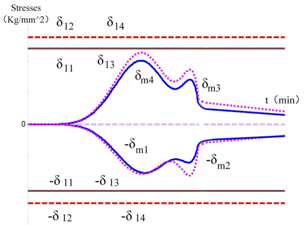
Figure 6: Variation trend of maximum stress of rotor.
When using ANSYS to analyze the starting process of rotor, it can be found that the stress concentration of the rotor is mainly concentrated in the regulating stage, the front groove of the regulating stage, and the root of the blade, as shown in figure 7 at points A, B, C and D.
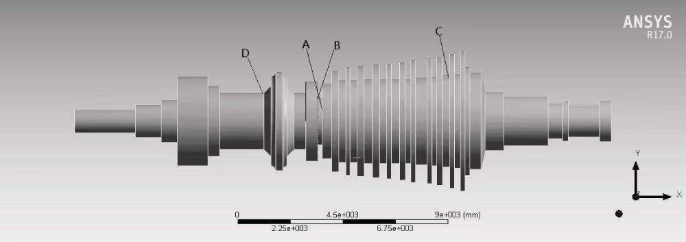
Figure 7: Location of stress monitoring points.
A. B, C, D are all marked as dangerous points, which should be paid more attention during the whole startup process. As long as the stress at these four points does not exceed the maximum stress that the material can bear, the stress at other parts is also safe. The analysis results of the whole cold start process are shown in figure 8.
Figure 8: Stress curve under original working condition.
From the results, four points A, B, C, D are processed in turn, and the stress changes of the regulating stage, the front groove of the regulating stage and the root of the blade can be seen. It can be seen from the above pictures that during the whole start-up process of the rotor, the max stress value appears at point a, and the maximum value is 446.24 Mpa. Compared with the start-up curve in figure 1. After warm-up at medium speed, the maximum stress of rotor appears. With the increase of speed, the derivative of temperature on the outer surface increases. After analyzing the start-up process stress value, the maximum stress is far from reaching the limit stress value, which leads to a long time of starting process, the starting curve in the initial conditions is too smooth, and the starting efficiency of the whole unit is poor. Through the calculation of the criterion formula, the effective stress value curve of the steam turbine during cold start is shown in figure 9.
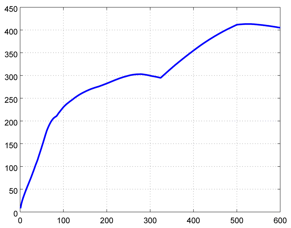
Figure 9: Effective stress curve of turbine rotor.
In order to facilitate the comparison, the effective stress curve superimposed by thermal stress and centrifugal stress is compared with the thermal stress curve. In the comparison, only the maximum part of the thermal stress, that is, the root of the impeller, is taken for comparison. The comparison figure is shown in figure 10.
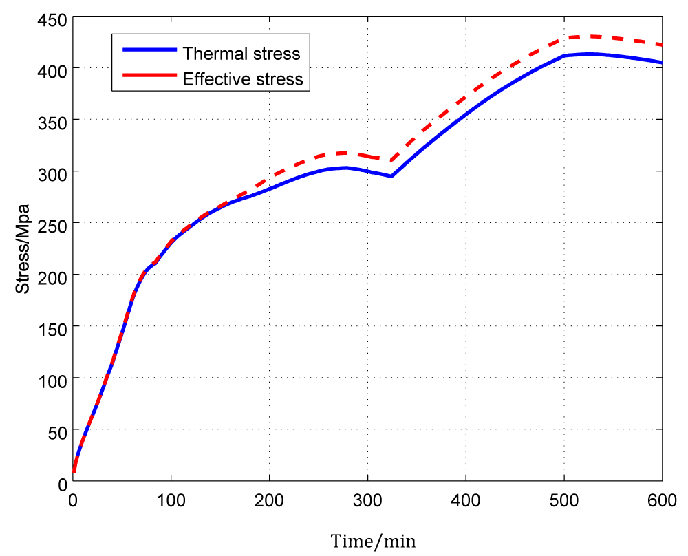
Figure 10: Comparison curve of effective stress and thermal stress of steam turbine rotor.
It can be seen from the figure that the centrifugal stress of the steam turbine rotor is directly related to the real-time speed. The centrifugal stress and the speed of the steam turbine are actually a problem of one-dimensional equation. With the increase of the rotor speed, the centrifugal stress increases. When the speed reaches the rated speed of 3000 r/min, the speed of the steam turbine will be constant, and then the centrifugal stress of the steam turbine will also be constant It is not difficult to see from the cold start curve that the speed of the turbine rotor rises to the rated speed of 3000 r/min in the 350th minute, and the centrifugal stress is basically maintained at this time. It is not difficult to see from figure 6 that when the turbine start time reaches 350 minutes, with the maintenance of the centrifugal stress, the change of the effective stress only changes with the change of the thermal stress, and there is a constant centrifugal stress in the middle the difference of stress.
Mathematical model of steam turbine start up process
The mathematical model of the start-up process of the rotor is mainly established according to the start-up procedures of the turbine. The detailed start parameters are shown in the cold start-up data curve of the rotor shown in figure 1. The start data of 300 MW turbine was collected from conventional power plant. As time goes on, the temperature and pressure of the boiler gradually increase. When the main steam temperature of the boiler reaches 260 oC, the steam pressure reaches 9.35 Mpa, and the steam turbine (turbine rotor) starts to rotate. The steam pressure is not higher than 0.8 MPa, and the vacuum degree of condenser is higher than -0.04 Mpa. When the rotor speed of turbine rises to 2054 r/min, the temperature rise rate of main steam temperature is 1.54 oC/min. when the main pressure reaches 370 oC, the preheating time of medium speed is calculated. During medium speed preheating, the time is 50 minutes. After medium speed preheating, the main temperature continues to increase. When the rotor speed of the steam turbine reaches 2942 r/min, the unit starts to be connected to the grid. Under the condition of different heating time, the main steam temperature rises to 538 oC within 550 min. After the start-up, the unit load reaches 74.67% of the total load in one hour, that is 224 MW. After synchronization, the generator load increases to the initial load at a certain load rate, and increases to the rated load again at different load rates after reaching the initial load holding time. The scheduling problem is to determine the scheduling parameters to minimize the starting time from the initial ignition of the boiler to the rated load of the generator, and to limit the maximum stress to a predetermined range. Therefore, the start-up scheduling problem can be formalized as a constrained function optimization problem, as shown in eq.5.
(5)
In the past, the research on optimization model of steam turbine start-up is to study the change of temperature rise rate of steam turbine start-up. Based on the temperature rise rate of steam turbine as a variable, the disadvantage is that the final temperature rise rate needs to be converted into time data, The steam turbine start-up optimization model studied in this paper takes the start-up time of each stage of the steam turbine as the variable, which greatly saves the amount of calculation and improves the efficiency of analysis. Aiming at the start-up process of 300 MW steam turbine, the paper analyzes each stage of the start-up process, including the cold start-up process of steam turbine rotor, the grid connection process of steam turbine, the shutdown process of steam turbine and the causes of stress. The thermal stress, centrifugal stress and effective stress of steam turbine rotor are analyzed by finite element analysis software ANSYS. According to the start-up process of steam turbine, the mathematical model of cold start-up of steam turbine is given, so as to further study the start-up optimization of steam turbine. When the main steam temperature of the boiler reaches 260 oC, the steam pressure reaches 9.35 Mpa, and the steam turbine (turbine rotor) starts to rotate. The steam pressure is not higher than 0.8 MPa, and the vacuum degree of condenser is higher than -0.04 Mpa. When the rotor speed to 2054 r/min, the temperature rise rate of main steam temperature is 1.54 oC/min. when the main pressure reaches 370 oC, the preheating time of medium speed is calculated. During medium speed preheating, the time is 50 minutes. After medium speed preheating, the main temperature continues to increase. When the rotor speed of the steam turbine reaches 2942 r/min, the unit starts to be connected to the grid. Under the condition of different heating time, the main steam temperature rises to 538oC within 550 min. After the start-up, the unit load reaches 74.67% of the total load in one hour that is 224 MW.
- Ahmed A, Robert E, Daniel L. et al. Low cycle fatigue life modelling using finite element strain range partitioning for a steam turbine rotor steel. Theoretical and Applied Fracture Mechanics. 2020; 113: 311-323.
- Ahmed A, Robert E, Mattias C, et al. Low cycle fatigue modelling of a steam turbine rotor steel, Procedia Structural Integrity. 2019; 23: 149-154.
- Yang YP, Li CZ, Wang NL, et al. Progress and prospects of innovative coal-fired power plants within the energy internet. Global Energy Interconnection. 2019; 2: 160-179.
- Xuanchen Z, Haofeng C, Fuzhen X, et al. On the creep fatigue and creep rupture behaviours of 9C12% Cr steam turbine rotor. Eur J Mechan. 2019; 76: 263-278.
- Janusz K, Mateusz B, Marcin J. The thermodynamic and economic characteristics of the modern combined cycle power plant with gas turbine steam cooling. Energy. 2018; 164: 359-376.
- Rusin A. The impact of the control method of cyclic operation on the power unit efficiency and life. Energy. 2018; 15: 565-574.
- Jan T, Dawid T, Karol K, et al. Monitoring of thermal stresses in pressure components based on the wall temperature measurement. Energy. 2018; 160: 500-519.
- Taler J, Dzierwa P, Taler D, et al. Optimization of the boiler start-up taking into account thermal stresses. Energy. 2015; 92: 160-170.
- Ji D, Sun J, Sun Q, et al. Optimization of start-up scheduling and life assessment for a steam turbine. Energy. 2018; 160: 19-32.
- Dettori S, Maddaloni A, Colla V, et al. Nonlinear Model Predictive Control strategy for steam turbine rotor stress. Energy. 2019; 158: 5653-5658.
- Seik P, Jugon S, Mitsuhiro M, et al. Validation of measured data on F/A ratio and turbine inlet temperature with optimal estimation to enhance the reliability on a full-scale gas turbine combustion test for IGCC. Int J Hydrogen Ene. 2019; 44: 13999-14011.
- Zhu XC, Chen HF, Xuan FZ, et al. On the creep fatigue and creep rupture behaviours of 9C12% Cr steam turbine rotor. Eur J Mechan. 2019; 76: 263-278.
- Ahmed A, Robert E, Daniel L. Low cycle fatigue modelling of a steam turbine rotor steel. Theoretical and Applied Fracture Mechanics. 2019; 23: 149-154.
- Saboya BI, Egido I, Lobato ME. MOPSO-tuning of a threshold-based algorithm to start up and shut-down rapid-start units in AGC. Int J Electrical Power Energy Systems. 2019; 108: 153-161.
- Dettori S, Maddaloni A, Colla V, et al. Nonlinear Model Predictive Control strategy for steam turbine rotor stress. Energy Procedia. 2019; 158: 5653-5658.
- Zhang Y, Benjamin D, Liu JB, Shen J, et al. Zone economic model predictive control of a coal-fired boiler-turbine generating system. Che Eng Res Design. 2020; 153: 246-256.
- Parag P, Babji S, Rajagopalan S. Process Fault Detection in Heat Recovery Steam Generator using an Artificial Neural Network Simplification of a Dynamic First Principles Model. Computer Aided Chemical Engineering. 2018; 44: 2065-2070.
- Milad M, Ali C, Amin R. An intelligent hybrid technique for fault detection and condition monitoring of a thermal power plant. Applied Mathematical Modelling. 2018; 60: 34-47.
- Mariusz B. The low-cycle fatigue life assessment method for online monitoring of steam turbine rotors. Int J Fatigue. 2018; 113: 311-323.
- Dettori S, Maddaloni A, Colla V, et al. Nonlinear Model Predictive Control strategy for steam turbine rotor stress [J]. Energy. 2019; 158: 5653-5658.
- Yu J, Liu P, Li Z. Hybrid modelling and digital twin development of a steam turbine control stage for online performance monitoring [J]. Renewable and Sustainable Energy Reviews. 2020; 133: 110077.\
- Hugo A, Pipino, Marcelo M, et al. Nonlinear temperature regulation of solar collectors with a fast adaptive polytopic LPV MPC formulation [J]. Solar Energy. 2020; 209: 214-225.