
More Information
Submitted: May 09, 2023 | Approved: July 24, 2023 | Published: July 25, 2023
How to cite this article: Vujović ŽĐ. Magnets, Gradients, and RF Coils of MR Scanners. Int J Phys Res Appl. 2023; 6: 128-135.
DOI: 10.29328/journal.ijpra.1001062
Copyright License: © 2023 Vujović ŽĐ. This is an open access article distributed under the Creative Commons Attribution License, which permits unrestricted use, distribution, and reproduction in any medium, provided the original work is properly cited.
Keywords: Main magnet; MR scanners; Cryostat; Superconductors; Gradient magnetic field; RF coils; Magnetic resonance

Magnets, Gradients, and RF Coils of MR Scanners
Željko Đ Vujović*
Boulevard Save Kovačevića 20/6-81000 Podgorica, Montenegro
*Address for Correspondence: Željko Đ Vujović, Boulevard Save Kovačevića 20/6-81000 Podgorica, Montenegro, Email: [email protected]
The topic of this paper is the parts of modern MR devices, which contain magnet coils. MR scanner magnets are made of four types of electromagnetic coils: 1) Main magnet, made of superconducting material. The main magnet of an MR (Magnetic Resonance Imaging) scanner creates a strong and uniform magnetic field around the patient being scanned. This magnetic field is typically in the range of 0.5 to 3 Tesla and is used to align the magnetic moments of the hydrogen atoms in the patient's body. The superconductors, which create the main magnetic field, should be cooled with liquid helium and liquid nitrogen. The main magnets made of superconductors should use a cryostat, with cooling vessels with liquid helium and liquid nitrogen, thermal insulation, and other protective elements of the magnet system. 2) The gradient magnetic field is made of three types of coils: x-coils, y-coils, and z-coils. The X coil, made of resistive material, creates a variable magnetic field, horizontally, from left to right, across the scanning tube; 3) The Y coil creates a variable magnetic field, vertically, from bottom to top; 4) The Z coil creates a variable magnetic field, longitudinally, from head to toe, inside the scanning tube. RF coils are used to generate RF pulses to excite the hydrogen protons (spins) in the patient's body and detect the signals emitted by the protons when they return to their equilibrium state after the RF excitation is turned off. The resulting interaction between the magnetic field and the aligned hydrogen atoms produces a signal that is used to generate the images seen in an MRI scan. The main magnetic field is what allows MR imaging to produce detailed anatomical and functional information non-invasively. The structure of the MR scanner magnet is complex. The resonant frequency changes at each point of the field in a controlled manner. Inside the copper core are embedded the windings of the main magnet made of superconducting material in the form of microfibers. A non-linear gradient field is created by coils of conductive material. It adds to the main magnetic field. Thus the resulting magnetic field is obtained. The types of magnets that exist in the basic configurations of MR scanners are analyzed. Scanners in the form of a closed cylindrical cavity generate their magnetic fields by passing current through a solenoid, which is maintained at the temperature of a superconductor. Exclusively used superconductors are niobium-titanium (NbTi), niobium-tin (Nb3Sn), vanadium-gallium (V3Ga), and magnesium-diboride (MgB2). Only magnesium diboride is a high-temperature superconductor, with a critical temperature Tc = 390K. The three remaining superconductors are low temperatures. New high-temperature superconductors have been discovered, as well as superconductors at room temperature. Newly discovered superconducting materials are not used in MR scanners.
This research was done to give an overview of the magnets used in modern magnetic resonance scanners, how they are made, and show their role and importance for obtaining final results and the purpose of using MR scanners: obtaining medical images of the internal organs of the human body. It was desired to describe these magnets and to show that these magnets are very complex devices, and the corresponding fields they create are very complex and composed of several components. Significant results on MRI magnets were provided by Allen D. Elster, ELSTER LLC. Those results were used "Courtesy of Allen D. Elster, MRIquestions.com" [1-4]. Apart from him, we highlight the results of Overweg J [5] and Cosmos TC, Parizh M [6]. The reason that prompted this research is the awareness of the phenomenon of electromagnetism and the colossal range it has reached in MR scanners, aided by superconductors. Standard methods of scientific and research work were used for the work. As the main results of this work, we present the description of the three components of the MR scanner's magnetic fields: the main magnetic field, the gradient magnetic field, and the RF field. MR scanner magnets are made of main magnets, gradient, and RF windings. The windings for the main magnets are made of superconducting materials and the windings for gradients and RF windings are made of resistant materials. The field created by the main magnet is necessary to bring the system of nuclear spins, on which it acts, to a state in which magnetic resonance is possible. The induction strength of the main magnetic field is the most important quantity for obtaining and for the strength of the magnetic resonance signal. Special importance is given to the consideration of superconducting materials used for the construction of MR scanner magnets. In this context, the first successful theory of superconductivity, the BSC theory, which revolutionized the field of condensed matter physics and opened up new possibilities for the application of superconductivity, is significant for this paper [7].
Almost all modern MR scanners use a superconductor made of niobium-titanium (NiTi), which becomes superconducting below 9,40K. Niobium-tin (Nb3Sn), vanadium-galium (V3Ga), and magnesium-diboride (MgB2) are also used. Only MgB2 is a high-temperature superconductor with a critical temperature Tc=390K. Nb3Sn is low temperature with Tc=18,30K and V3Ga low temperature with Tc=14,20K. [8] Gradient systems produce calibrated distortion of the main magnetic field in the x-, y- or z- direction. RF coils are responsible for perturbing the nuclear spin system, while Patient coils are responsible for MR signal detection. New high-temperature superconducting materials have been discovered as well as room-temperature superconductors, (Tl5Pb2) Ba2Mg2Cu9O18+, Tc=280K(3100K/550K) and (Tl5Pb2) Bu2Mg2,5Cu85,O17+, Tc=300C(3030K/580F) are given as an example. The hypothesis that main magnets could be made of high-temperature superconductors and room-temperature superconductors has not been proven. On the contrary, it has been shown that this is, for now, impossible because there are many difficulties in the application of newly discovered superconductors (instability in the magnetic field, low current density, the need to make high-quality and extremely expensive materials…). All practical solutions must be cooled at this time. Magnetom Terra 7T scanner from Siemens Healthcare, the first ultra-high-field MR scanner approved for clinical use. Noise level: base load ≤ 56.7dB (A) 8, full load ≤ 102.2dB (A) 8. Siemens promoted it as a revolutionary innovation [9]. A superconducting magnet is an electromagnet made from superconducting windings. During operation, the windings must be cooled below their critical temperature, at which they pass from the basic state to the superconductor state. A cryostat is a system for maintaining a very low temperature. It is thermally insulated from the environment. A typical cryostat, used in MR scanners, consists of three vessels, located one inside the other. The outer vessel is filled with a vacuum. It acts as a thermal insulator. Beneath this vessel is a vessel filled with liquid nitrogen. It serves as a protection, insulation, and middle shield, which prevents the action of heat from the outer vessel, on the inner vessel. The inner vessel contains cryogen (cooler-liquid helium). Low-temperature, high-temperature, and room-temperature superconductors [10]. Gradients are made of windings of resistive conductors.
It was hypothesized that the main magnets of the MR scanner could be made from high-temperature superconductors and room-temperature superconductors.
The complete magnetic field of an MR scanner is shown, which is generated by three main components: the main component that generates the magnetic field, the component that generates the gradient magnetic field, and the component that generates the radiofrequency (RF) magnetic field.
Principle of implementation of MR scanner magnets (Figure 1).
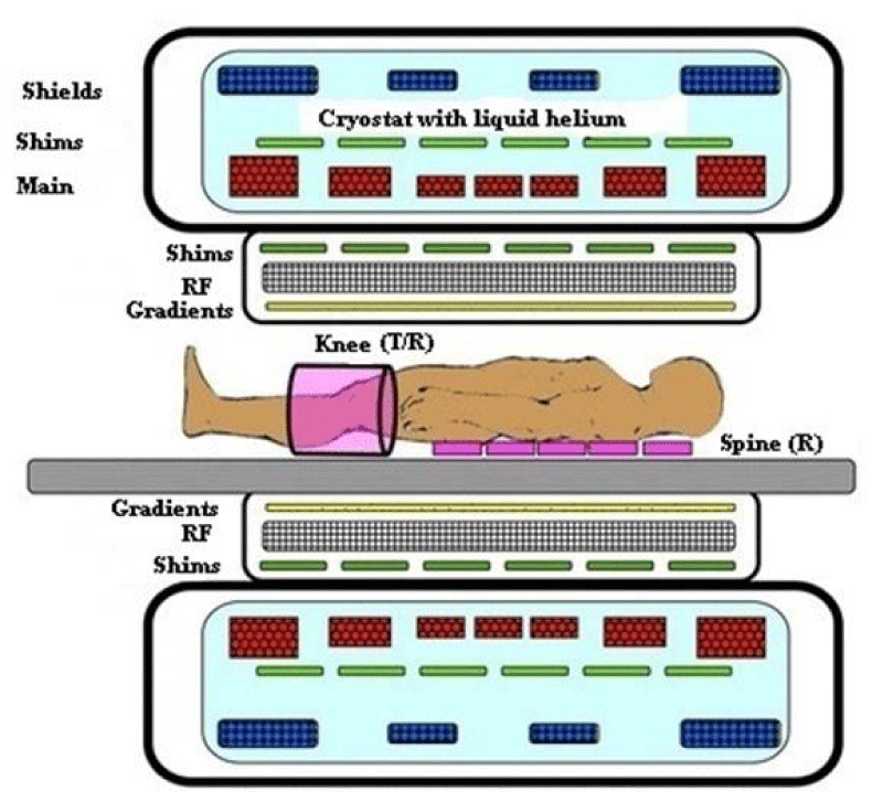
Figure 1: Representative cross-section of a superconducting scanner showing the nest "coils" nested arrangement". Both superconducting and resistive backing coils are shown. Two types of patient coils are also illustrated: a receive-only spinal coil array and a transmit/receive knee coil [11].
Metal cover of MRI scanner (Figure 2).
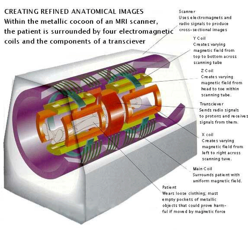
Figure 2: Representative cross-section of a superconducting scanner, showing the nested arrangement of "coils". Both superconducting and resistive coils are shown. Two different patient coils are illustrated: Spinal Chain Receiver Only and Knee Emitter/Receiver [12].
Main magnet from superconductive material in cryostat (Figures 3,4)
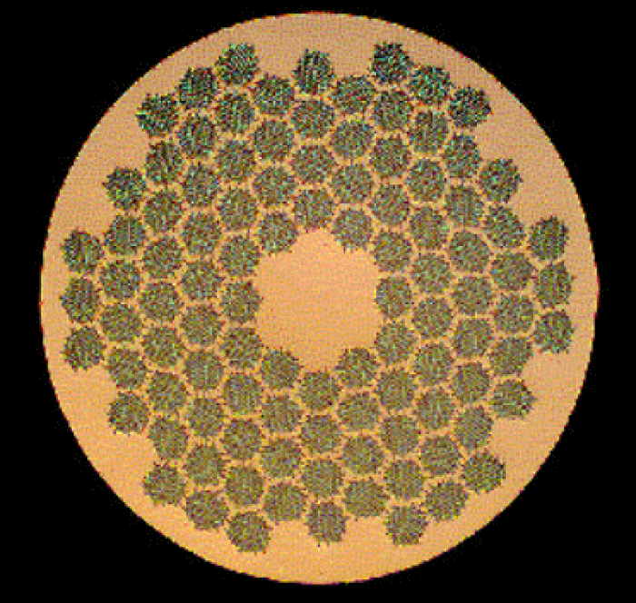
Figure 3: Cross-section of a superconducting multi-microfiber NbTi coil embedded in a Cu core [13].
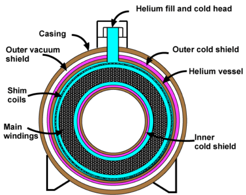
Figure 4: Representative cross-section of a typical superconducting magnet (designs vary). Liquid helium chambers are green-blue [13].
Gradient magnetic field coils (Figures 5-8)
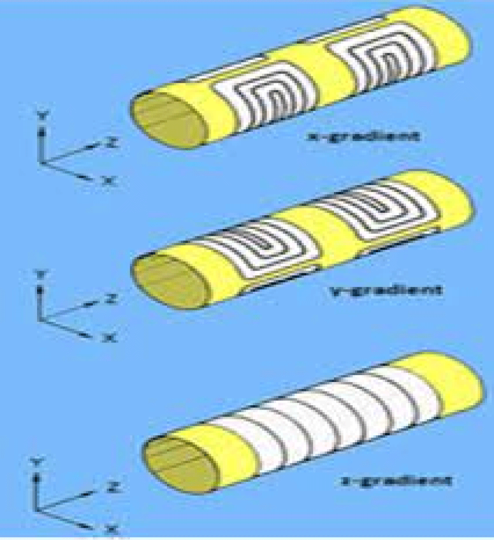
Figure 5: Gradient windings for the three basic directions Gradients x and y act only to create a "tilt" of the z-component B0 [14].
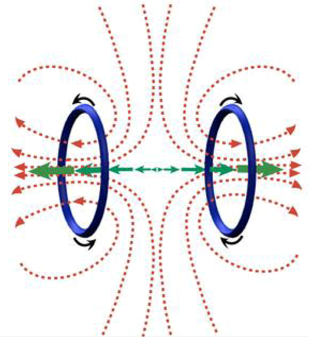
Figure 6: Maxwell Couple - The z-axis gradient is based on the concept of a Maxwell coil, two loops that carry current in opposite directions. The gradient field (large red arrows) is zero in the middle, but becomes stronger in the +z and -z directions [15].
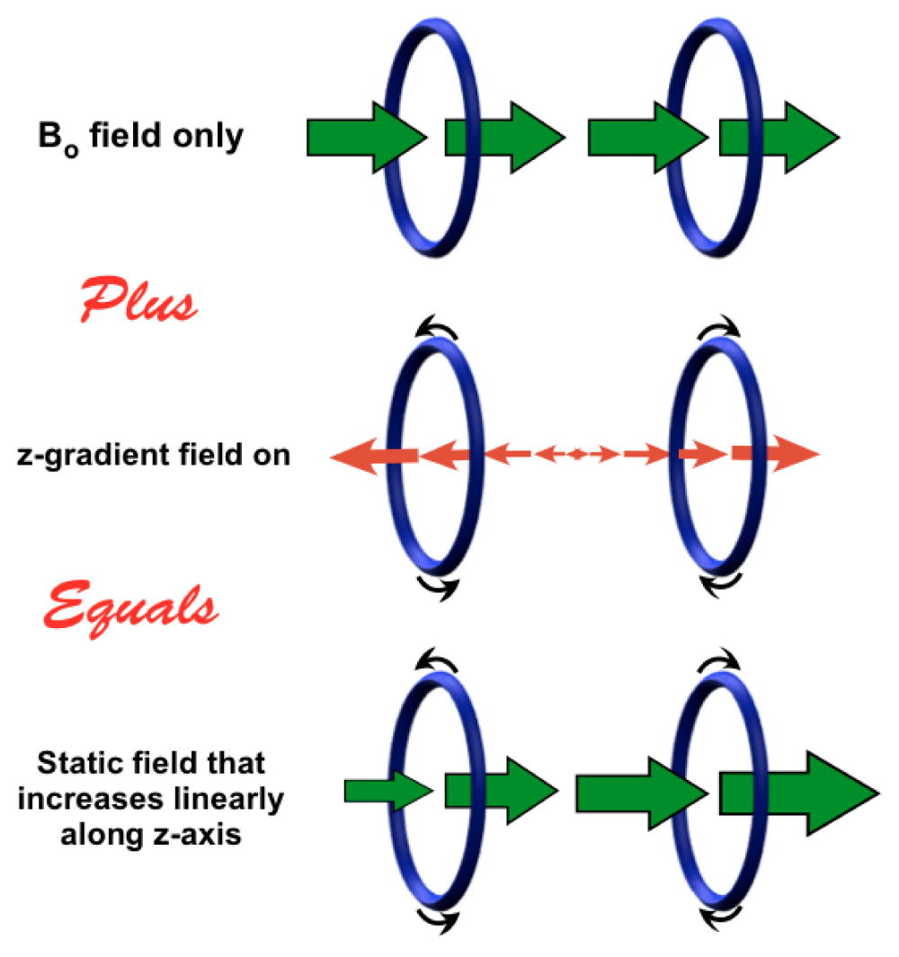
Figure 7: Diagram showing how the z-gradient field is added to the base field B0, to obtain a field that increases linearly from –z to + z [15].
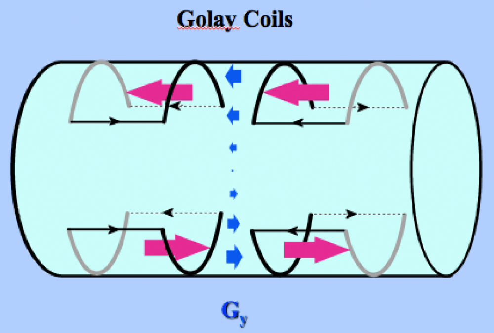
Figure 8: Configuration of a double saddle coil (Golay) for y-gradient production. To produce the x-gradient, the coils are rotated 900 along the surface of the cylinder [16].
System of gradients (Figure 9)
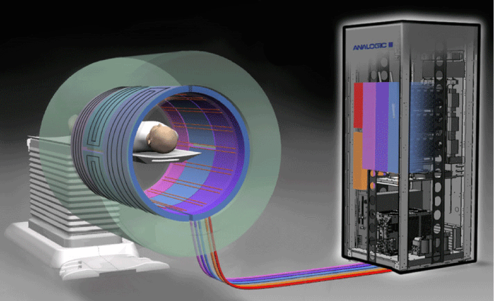
Figure 9: A complete gradient system showing coils positioned along the inner bore of the scanner driven by powerful current amplifiers and cooled by water chillers in the adjacent MR equipment room. (Radio frequency (RF) coils, which are located within the gradient coils, are also shown in the figure [14].
Radiofrequency coils (Figures 10,11)
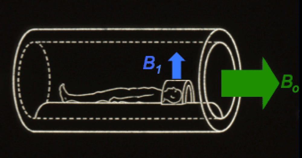
Figure 10: RF – transmit coils [17].
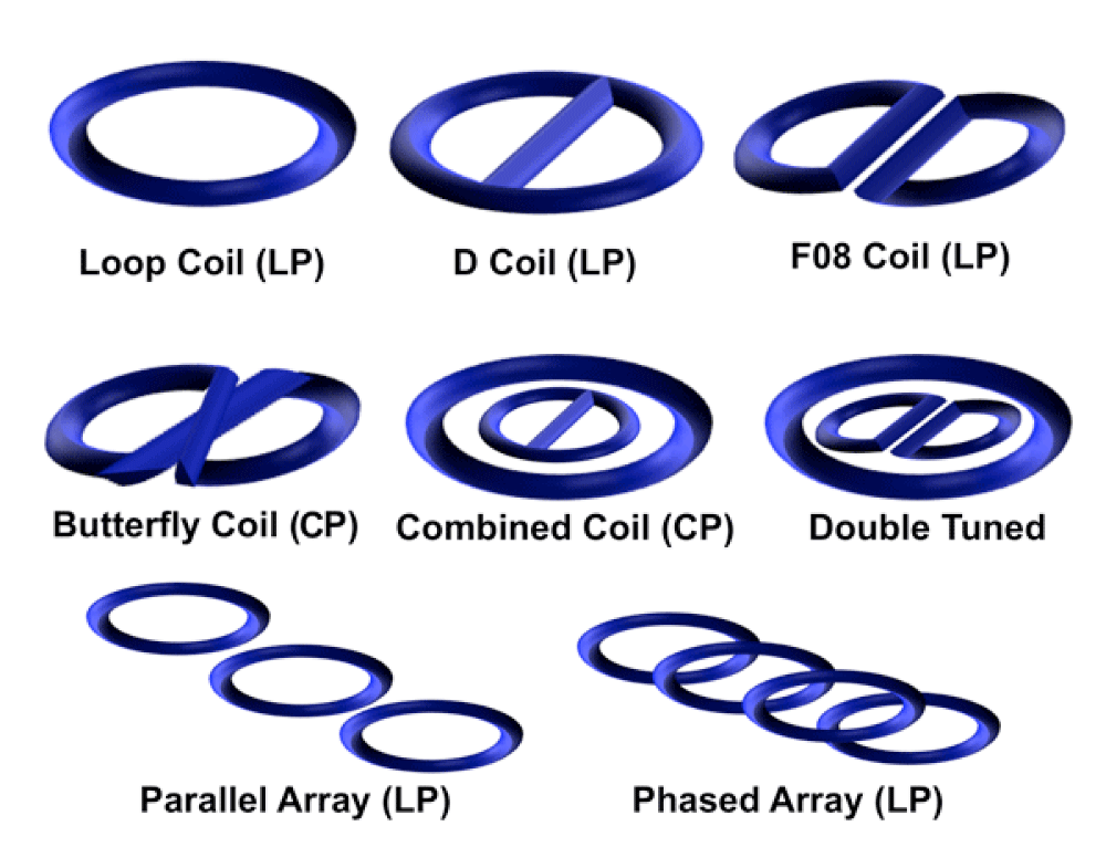
Figure 11: Receive–only RF coils [18].
A general view of the principle of realization of the magnet of the MR scanner (Figure 1) starts from the shields of the MR scanner. Shields are specialized devices or materials used to minimize or control electromagnetic interference from the external environment. There are several types of these shields. The purpose of the radio frequency shield [19] is to keep the RF signals generated by the MRI system in the room, preventing them from escaping and causing interference with external devices. At the same time, this shielding serves to block external RF signals from entering the MRI room and interfering with the MRI network. In the MRI room, a Faraday cage is also used as a shield [20]. It consists of conductive walls, floor, and ceiling, made of copper or aluminum. These materials block the external EM field from entering the room and interfering with the recording process. At the same time, the Faraday cage keeps the magnetic field generated by the machine in the room, preventing it from affecting nearby electronic devices or causing potential safety hazards. A special type of shield is magnetic protection (active and passive) [20]. It is the process of reducing magnetic fields to minimize their impact on the recording environment. It is achieved by using different materials and design techniques to confine the magnetic field within the recording area. Magnetic protection is performed as ferromagnetic protection, Radio Frequency (RF) protection, door and window protection, and gradient winding protection, which can be thermal, electrical, mechanical, electrical isolation, monitoring, and control system. EMI (Electromagnetic Interference) filters, designed to mitigate interference caused by the MRI system, are also used as shields. They suppress or attenuate unwanted electromagnetic noise and harmonics generated by the MRI system. Shims [20] are additional sets of coils within the MRI system. They are used for fine-tuning and optimization of the homogeneity of the main magnetic field. These coils produce localized magnetic fields to compensate for any inhomogeneities or variations in the magnetic field that may occur. By modulating the current through these coils, the main static-magnetic field is adjusted to improve image quality or minimize distortion. The structure and position of the magnetic coils are shown in Picture 1. Main field (B0) Coils – Principal magnet windings plus superconducting shim and shield coils: Produce B0, Shim Coils – to improve homogeneity, Gradient Coils – for creating magnetic field gradients that provide spatial information about the origin of the signals emitted by protons in the patient's body. A complete gradient system consists of coils mounted along the inner bore of the system. Produces calibrated distortion of the main magnetic field in the x–, y– or z– direction. Radiofrequency (RF) Coil – transmits B1 field, Patient Coils – primarily to detect MR signal, some are transmit/receive. The radiofrequency (RF) system–coils are responsible for perturbing the nuclear spins and recording MR signals [11].
A "nested" arrangement of coils is used for RF coils (Figure 2). It is a configuration where multiple RF coils are placed inside each other. The coils placed in this way are used to emit and receive RF signals [20] based on which MRI images are generated. A nested winding arrangement consists of two or more windings of different sizes. A larger coil called a body coil or emitter coil, is placed around the patient's body and emits RF pulses. Smaller coils, called receiver coils or local coils, are placed closer to a specific area of interest to pick up the RF signals emitted by the excited protons. The main magnet is created by microfibers, strings made up of multiple fibers (such as nylon), which are twisted together. Figure 3 shows an example. The microfibers of one of the superconductors, NiTi, Nb3Sn, Va3Ga, or MgB2, are inserted into the copper conductors. Copper acts as an insulator at low temperatures, relative to the zero resistance of the microfiber alloy, supports and protects alloy windings from damage provides mechanical strength, and prevents deformations and vibrations. It takes over the conduction of electricity, if, due to a fault, the superconducting mode is lost (Quench).
The cryostat [20] (Figure 4) is a cylinder with a circular or oval cross-section. It is used to create and maintain cryogenic temperatures. Cryogenic temperatures are extremely low temperatures below -1500C or 1230K. Cryogenic temperatures are achieved using specialized equipment and cryogenic fluids, such as liquid nitrogen or liquid helium. Certain materials, metals, and alloys, acquire the property of superconductivity at cryogenic temperatures. Superconductors conduct electricity with zero resistance (no resistance). Many gases become liquid at cryogenic temperatures. For example, helium becomes liquid helium at temperatures below -268,930C. The cryostat in Figure 4 has a special container that is filled with liquid helium. The container thus filled becomes a "cold head", which serves to cool the microfibers and bring them to a state of superconductivity. The superconducting microfibers thus obtained create the main magnetic field of the MR scanner. The cryostat in Figure 4 is made of components arranged from outside to inside, in the following order: protection case, outer vacuum shield, outer cold shield, helium vessel ("cold head"), backing coils, main windings, and inner cold shield.
The main magnetic field of the MR scanner has two basic purposes
1. Polarization of nuclear spins: The main magnetic field aligns the nuclear spins of atoms inside the patient's body. In MRI, the most commonly imaged nuclei are hydrogen atoms (protons). When exposed to a strong magnetic field, these cores (protons) align parallel or antiparallel to the field. This polarization is necessary for subsequent steps in the imaging process.
2. Creation of reference frame: The main magnetic field establishes a stable reference frame for measuring radio frequency signals. The reference frame of the main magnetic field is typically defined as the laboratory frame or static magnetic field, denoted as B0. During an MRI scan, radiofrequency pulses are applied to the patient's body. These pulses cause the polarized protons to absorb and re-emit energy, which is detected by the MRI system. The strong and uniform main magnetic field enables the MRI system to accurately measure the properties of the emitted radiofrequency signals and reconstruct high-quality images. Protons in a magnetic field absorb and emit electromagnetic energy (MR signals) at the Larmor frequency [20]. It is a characteristic frequency associated with the precession of the magnetic moment of atomic nuclei (spin). It is directly dependent on the strength of the magnetic field experienced by the protons and is given by the Larmor equation: ꭃ = γ*B. (ꭃ is the resonant frequency in radians per second, γ is the gyromagnetic ratio - a constant that is specific to the nucleus being recorded; for protons, it is approximately 42.58 MHz/T, B is the strength of the magnetic field in terms. The MR signal is generated by the interaction of the magnetic field and the spins of atomic nuclei (hydrogen protons) in the body. The MR signal is characterized by parameters: amplitude, frequency, phase, T1 relaxation time, T2⁕ relaxation time, echo time (TE), and repetition time (TR) [21].
In the case of a superconducting magnet [20], the power supply is connected on both sides of the coil segment. The current through the coil increases gradually, over several hours, until the desired field is reached. The current continues to flow in a closed loop, without a significant drop. The resulting property is that the magnetic field is always present. The construction of superconducting magnets is considered to be extremely expensive, and cryogenic helium is expensive and difficult to maintain. Nevertheless, today they are the most common type of magnet found in MRI scanners. It is estimated that investing in the production of new usable superconductors would be a process that does not pay off.
The gradient [20] of the magnetic field is the difference of the magnetic field, in magnitude or direction, between two points in space: G=ΔB/Δl. By applying different gradients in space, signals from different parts of the body can be differentiated and used to generate detailed images with spatial information. Gradient coils [19] are conductive loops of thin conductive sheets on a cylindrical shell that lies inside the opening of the MR scanner. The current, which is passed through this coil, creates a secondary magnetic field. This secondary magnetic field is gradient. It slightly changes the shape of the main magnetic field in a predictable way. This causes the resonance frequency of the proton, the Larmor frequency, to vary depending on the position, and the place in the newly created magnetic field. Modern MR scanners use, as gradient coils, distributed coils in a "fingerprint" pattern, consisting of multiple thin metal strips or large scalar sheets etched into complex patterns and applied to a cylinder. All MR systems use three sets of coils: x–, y–, and z– [14]. Each of these sets of coils excites an independent power amplifier and creates a gradient magnetic field, which causes the z component of the main magnetic field to vary. The components of the gradient magnetic field x– and y– do not distort or move the main magnetic field B0. They change this field in the z-direction. The application of the gradient magnetic field changed the total magnetic field in which the protons are located and processed. Since the resonant frequency of the proton depends on the magnitude of the magnetic field in which the proton is located, the resonant frequency of the proton will change along the direction of the gradient [22].
A linear gradient is added to the main magnetic field, a balanced disturbance of the fundamental field along the axis of the magnet (x-side-side, y-front-back, z-head-heel). The cross-section of all three axes is the isocenter of the magnet. In it, the basic magnetic induction has, always, the same value. The construction of the z-gradient is usually based on circular coils, (Figure 6) while the transverse (x-and y-) gradients typically have a saddle winding configuration (Figure 8). More precisely, the basic design of the z-direction gradient is Helmholtz's pair of coils: two loops with currents flowing in opposite directions. Maxwell coil pair [20] produce a gradually changing field, which is zero in the magnetic isocenter but increases linearly outward, in both directions + z and -z. When this is added to the constant field B0, the result is a gradual increase along the z-axis gradient (Figure 7). With the help of gradient windings, the value of the strength of the magnetic induction at each point of the three-dimensional space of the magnet is changed in a controlled manner. The resonant (Larmor) frequency is proportional to the strength of the magnetic induction. So, it has been achieved that the resonant frequency changes, controlled in every point of three-dimensional space. This also means that the magnetic resonance signal is different at each point. The signal strength is proportional to the spin concentration at the observed point. The concentration of spins in various parts of the sample can be determined by measuring the magnetic resonance signal [14].
Three sets of gradient coils are used in nearly all MR systems: the x-, y-, and z- gradients. Each coil set is driven by an independent power amplifier and creates a gradient field whose z-component varies linearly along the x-, y-, and z- directions, respectively. The design of the z-gradients is usually based on circular (Maxwell) coils, while the transverse (x- and y-) gradients typically have a saddle (Golay) coil configuration (Figure 8) [16].
Maxwell's coils produce an incremental field (gradually, gradually added in successive steps), which is zero at the isocenter of the magnet but grows linearly outward in both the +z and –z directions. When this is added to the constant field (B) the result is a gradual increase in the field in both the +z and –z directions. The magnetic isocenter [20] is the point within the magnetic field where the magnetic field is the most homogeneous. The Maxwell pair is a variation of another z-coil arrangement - the Helmholtz coil. In the Helmholtz configuration, the current in the two coils is in the same direction, while in the Maxwell coils the currents flow in opposite directions. Helmholtz coils are used to generate the main magnetic field (B0), while Maxwell coils are used to generate the z-gradient field (Gz) [14]. Figure 7 shows how the main, static magnetic field increases along the z-axis when a z-gradient field is added to it.
The design for transverse gradients used in cylindrical MR magnets is based on a "double/saddle" coil configuration (Figure 8) – Golay coil [20]. The simplest form of this set of coils consists of 4 inner and 4 outer arcs on the surface of the cylinder connected by 8 straight conductors running parallel to the z-axis. The current along the internal arcs is primarily responsible for creating the required gradient, while the straight conductors, parallel to the z-axis, serve as return paths for the current and do not contribute to the gradient field. The homogeneity of a simple Golai configuration is significantly improved by adding more arcs and curves. Eight straight conductors parallel to the z-axis, in Golai configuration, cannot affect the z-component of the magnetic field (Bz), they produce transverse components (Bx and By). These transverse components (not to be confused with the x- and y-gradients, which are spatial derivatives of Bz) are called "accompanying" or "Maxwellian" fields. These fields do not directly affect the localization of the MR signal, but they do contribute to the total magnetic field experienced by the patient, so they must be taken into account when considering certain biological effects of the gradients. Figure 9 shows the actual appearance of the gradient coils, connected by electrical conductors to the adjacent room from which they receive the necessary electrical power [16].
RF coils (Slika 10) are positioned strategically around the region of interest to transmit RF pulses and receive the resulting signals. These coils are designed to interact with the magnetic field and the body tissues, enhancing the imaging process's sensitivity and resolution. There are two main categories of RF coils: 1) Transmit Coils – generate the RF electromagnetic field that excites the protons in the tissue, causing them to emit a detectable signal. Transmit coils can be limited to an MRI machine or placed near the patient's body using specific designs, such as body coils or surface coils. 2) Receive Coils – are used to capture the emitted signals from the patient's body. They are designed to detect weak radiofrequency signals that can be processed and reconstructed into an image. Receive coils can be integrated into the MRI machine or employed as separate components, such as head, spine, or joint coils.
There are four types of RF coils: 1) Surface Coils – flat or curved coils placed directly or near the area of interest. They are designed to image specific body parts, such as the head, knee, spine, or breast. 2) Volume Coils (Body Coils or Birdcage Coils) [20] – large coils that encircle the entire body or a significant portion of it. They are used for whole–body imaging or to cover larger anatomical regions, such as the torso or extremities. 3) Phased Array Coils – consist of multiple smaller coil elements arranged in an array. 4) Head Coils – designed specifically for imaging the brain. They often have a helmet–like shape that fits over the head and incorporates multiple small RF coil elements to provide detailed brain images. 5) Flex Coils – flexible and adaptable coils that can confirm different body parts’ contours, providing optimal signal reception and patient comfort. They are particularly useful for imaging joints and extremities [23]. The diagram of RF coils in Figure 10 shows the transmit-receive head coil in an MR system. RF transmission requires a separate field (B1) rotating/oscillating near the proton resonant (Larmor) frequency directed perpendicularly to the main magnetic field (B0) [17]. The receiving coils are shown in Figure 1 and may be placed differently, depending on the area of interest to record. Receive coils are usually placed directly on the patient. In Figure 11 are various loop coil configurations (LP–linearly polarized; CP–circularly polarized/quadrature) [18].
To remind ourselves: what happens in an MRI system when the frequency of the RF signal is close to the Larmor frequency?
The Larmor frequency refers to the body tissues’ process or resonance in response to a strong main magnetic field. When the RF signal used in an MRI system is close to the Larmor frequency, several important phenomena occur 1) Resonance – In that case, it matches the resonant frequency of the protons in the magnetic field, leading to efficient energy transfer [ꭃ = γ*B]. This resonance phenomenon is critical for manipulating the protons in the body during MRI. 2) Signal Excitation – RF signal is used to excite the protons in the body tissue. In that case, the protons absorb energy and transition from a low–energy state to a high-energy state. This excitation process prepares the protons for subsequent signal excitation and imaging. 3) Signal Detection – After the excitation phase, the MRI system switches off the RF excitation, allowing the protons to return to their low–energy state. As they relax, the protons emit energy in the form of electromagnetic signals. These signals, known as free induction decay (FID) [20], are detected by specialized RF receiver coils in the MRI system. 4) Image Formation – The detected signals undergo a series of processing steps to construct an MRI image. By manipulating the RF pulses and timing, different tissues can be selectively excited and imaged, The RF frequency᾿s proximity to the Larmor frequency affects the contrast and sensitivity of the resulting image, as it determines which protons resonate and contribute to the detected signal.
When used as transmitters, the RF coils create a mirroring/rotating magnetic field (B1), which is normal to the main static magnetic field (B0). If the B1 oscillation is close to the Larmor precession frequency of the nuclear spins, energy is deposited into the spin system, causing a change in its net alignment with the direction of the main magnetic field. Field B1 is generated by the RF transmission coil in response to the strong current generated by the scanner's transmission circuit. B is usually switched on only for short time intervals (a few ms), called "RF-pulses". By adjusting the size and duration of these B1 pulses, the nuclear spin system can rotate through variable spin angles, such as 900 or 1800. When used as receivers, RF coils detect MR signals. The oscillating net magnetic flux from the excited spin system is detected by the coil which generates an induced electric current. This current is then digitized and filtered to extract frequency and phase information.
To achieve the superconductivity of the material, which creates the main magnetic field, a cryostat is used, with cooling vessels for liquid helium and liquid nitrogen, thermal insulation, and other elements to protect the main magnet system. These elements determine the dimensions and size of the device. Initially, nitrogen should be replenished weekly and helium monthly. This was gradually perfected, so liquid helium had to be replenished every 2–3 years. There are data that, lately, zero temperature cooling systems (ZBO) have become the standard.
Unlike a conductor, a superconductor conducts electricity indefinitely, without energy losses. This is an important characteristic of these materials and a challenge for their use. They do not lose electricity! For the main magnets of MR scanners are used: niobium-titanium (NbTi), Tc=10K, B0~15T (Since 1960), niobium-tin (Nb3Sn), Tc=18,30K 254.80C / -426.7F), B0~25T to 30T (Since 1960), vanadium-gallium (V3Ga), Tc = 14.20K, B0~19T, magnesium-diboride (MgB2), Tc=390K (-2340C / -3890F) (Since 2001). It can be noticed that out of four superconductors, three are low-temperature and one is high-temperature.
Professor Allen D. Elster states that there is, in the experimental phase, re-production of MR scanners using "high temperature" superconductors. An example is magnesium-diboride (MgB2), with a critical temperature of Tc = 390K and others. In the future, he envisions using these superconductors to build MR scanners. This was an incentive for digression from the main topic of this paper and a review of the current state and chronology of superconductors. It can be seen that a significant number of high-temperature superconductors and room-temperature superconductors were discovered. Their application in practice is far away. The question is whether and when, these superconductors will be usable because of the properties they have. From the chronology of the discovery of superconductors, the following events can be singled out as markers: 1941. Niobium-nitride, Tc = 1600K, 1945. described by Perovskite, 1962. made the first commercial superconductor NbTi. At that time the use of niobium-tin, Nb3Sn, began. In 1972, the BSC theory of superconductivity (Burden-Cooper-Schiffer) was published. 2001. described by MgB2 [7].
This study confirmed, as important, that room temperature superconductors, although discovered, are not in the field of research of the world's leading laboratories, as possible materials for making magnets for MR scanners. Their indisputable discoveries are imposed, for research and application. The current situation is such that there is no known scientific method by which they could be turned into useful, applications, which should be eliminated. It is estimated that research to achieve this is extremely expensive. Scientific optimism gives hope that it is a matter of time before they become applicable, and that the practical benefits of their discovery will be obtained.
This work is important primarily because it explains the complex structure of the MR scanner magnets and how the three main magnet fields are produced by proper coils. The principle of the realization of the scanner, the cross-section of the winding of the superconducting magnet with microfibers in a cryostat, the principle of creating a nonlinear gradient and its role in creating the resulting magnetic field as well as radiofrequency field, produced by the radiofrequency coils for excitation of a spin system in the patient᾿s body, body coils for receiving signals from spin systems during their relaxation time, returning to the equilibrium state existing prior excitation. The phenomena that occur when the radiofrequency of the excitation pulses is close to the Larmor frequency have been considered. In that case, the phenomenon of magnetic resonance enables more efficient energy transfer, excitation of the spin system with an RF signal, and detection of an emitted signal after the termination of the RF excitation, after which the processes that form the image are carried out. These processes are hinted at as the possibility of new work that could be created based on this work. That work would consider spatial encoding of transmitted signals, frequency, and phase, the transformation of obtained data by Fourier transformation, arrangement of detected raw signals in the k-space matrix, application of inverse Fourier transformation, and other things needed to obtain the required image of the internal organs of the human body. The paper emphasizes the importance of the discovery of high-temperature superconductors and room-temperature superconductors, which were awarded Nobel prizes, but also the delay in applying these discoveries for practical purposes. There are objective reasons for that. The initial assumption that the main magnets of MR scanners are made of high-temperature superconductors and room-temperature superconductors has not been proven. On the contrary, it turned out that these superconductors cannot be used to make the main magnets of MR scanners. If and when the newly discovered superconductors are brought to a practically applicable level, this remains a possible idea for some future work. There are no new proposals for MR scanner main magnets.
- Elster DA, MR magnet types. (Accessed 18.07.2023.). Questions and Answers in MRI. https://mriquestions.com/types-of-magnets.html
- Elster DA, Magnets II. (Accessed 18.07.2023.). Questions and Answers in MRI. https://mriquestions.com/magnets---part-ii.html
- Elster DA, Magnetic gradients. (Accessed 18.07.2023.). Questions and Answers in MRI. https://mriquestions.com/gradients.html
- Elster DA, RF and Coils. (Accessed 18.07.2023.). Questions and Answers in MRI. https://mriquestions.com/rf--coils.html
- Overweg J, MRI main magnets, Presented ISMRM 2006.
- Cosmus TC, Parizh M. Advances in Whole-Body MRI magnets. IEEE Transactions on Applied Superconductivity. 2011; 21(3): 2104–2109. https://doi.org/10.1109/tasc.2010.2084981
- Bardeen J, Cooper LN, Schrieffer JR. Theory of Superconductivity. Physical Review. 1957; 108:5.
- Flukiger R. MGB2 superconducting wires: Basics and Applications. World Scientific. 2016.
- Siemens Healthcare Gmbh©2023 Corporate, MAGNETOM Terra. (Accessed28.04.2023.). https://www.siemens-healthineers.com/magnetic-resonance-imaging/7t-mri-scanner/magnetom-terra
- J Eck. Superconductors. (Accessed 29.04.2019.). http://www.superconductors.org/
- Mri coils, Slideshare, Jun 28, 2020, slide 17, Mri coils. (Accessed 19.07.2023.). https://www.slideshare.net/sonysahs/mri-coils
- Jaiswal D. Applications and Comparison of Medical Imaging Modalities. 2018. https://www.semanticscholar.org/paper/Applications-And-Comparison-of-Medical-Imaging-Jaiswal/a2e07302941a378d9666dbe2d90788507516533c
- Elster DA, Superconductive magnet design. (Accessed 19.07.2023.). Questions and Answers in MRI. https://mriquestions.com/superconductive-design.html
- Elster DA, Gradient coils. (Accessed 19.07.2023.). Questions and Answers in MRI. https://mriquestions.com/gradient-coils.html Gradient coils
- Elster DA, Z-gradients. (Accessed 19.07.2013.). Questions and Answers in MRI. https://mriquestions.com/how-do-z-gradients-work.htmlZ–gradients
- Mri gradient coils, slide 18. (Accessed 19.07.2013.). https://www.slideshare.net/ShahnawazKhan277/mri-gradient-coils
- Elster DA, RF transmit coils. (Accessed 19.07.2023.). Questions and Answers in MRI. https://mriquestions.com/rf-transmit-coils.html
- Elster DA, Receive only MR coils. (Accessed 19.07.2023.). Questions and Answers in MRI. https://mriquestions.com/receive-only-coils.html
- Elster DA, Radiofrequency (RF) – Shielding. (Accessed 20.07.2023). https://mriquestions.com/why–rf–shielding. html
- Glossary of MRI Terms, American College of Radiology. ACR.org home. (Accessed 20.07.2023.). https://www.acr.org/
- Elster DA, Larmor Frequency. (Accessed 20.07.2023). https://mriquestioncom./why–at–Larmor–frequency. html
- Elster DA, Magnetic Field Gradient Defined. (Accessed 20.07.2023). https://mriquestions.com/what–is–a–gradient. html
- Elster DA, Radiofrequency Coils. (Accessed 20.07.2023). https://mriquesti2ons.com/rf–coil–functions. html