
More Information
Submitted: April 21, 2025 | Approved: May 14, 2025 | Published: May 15, 2025
How to cite this article: Aliyev ZH, Abbas AV, Sardar NM, Yagub NS, Haji AB. Study of Tribological Properties of Disc Mills Wear in Furniture Production. Int J Phys Res Appl. 2025; 8(5): 116-119. Available from:
https://dx.doi.org/10.29328/journal.ijpra.1001120
DOI: 10.29328/journal.ijpra.1001120
Copyright license: © 2025 Aliyev ZH, et al. This is an open access article distributed under the Creative Commons Attribution License, which permits unrestricted use, distribution, and reproduction in any medium, provided the original work is properly cited.
Keywords: Uniform wear; Sharpening; Chipboard; Disc mills; Cutting edges

Study of Tribological Properties of Disc Mills Wear in Furniture Production
ZH Aliyev1*, Abbasov Vagif Abbas2, Nasirov Mursal Sardar3, Novruzova Sevinj Yagub4 and Aliyev Balakhan Haji5
1Institute of Soil Science and Agrochemistry of ANAS, Azerbaijan
2Professor, Doctor of Technical Sciences, Department of Special Technologies and Equipment, Azerbaijan Technical University, Baku, Azerbaijan
3Lecturer, Department of Mechanical Engineering, Baku Engineering University, Baku, Azerbaijan
4Senior Lecturer, Department of Electrical Power Engineering, Nakhichevan State University, Nakhichevan, Azerbaijan
5PhD, Docent/Associate Professor, Department of Mechanical Engineering, Baku Engineering University, Baku, Azerbaijan
*Address for Correspondence: ZH Aliyev, Professor, Institute of Soil Science and Agrochemistry of ANAS, Azerbaijan, Email: [email protected]
The article is devoted to the study of the tribological behavior, particularly the wear mechanisms and the shape of the cutting surfaces of Disc mills for various purposes and designs when processing furniture parts made of various wood materials. The changes in the length of the cutting edge of a cutting tool with soldered teeth made of hard alloy were calculated when processing grooves on chipboard and MDF. All results are presented in tables and graphs generated using Microsoft Excel. At the end, the recommendations to enhance tool condition and longevity and carry out further work in this area are summed up.
Wear is the gradual loss of material from the surface of a cutting tool after mechanical or chemical wear during the relative movement of the tool with the machined surface. In addition, wear is a tribological phenomenon that occurs when two loaded bodies are in contact and relative motion and due to friction between the cutting tool and the wood or wood product, which progresses over time depending on cutting conditions, depending on the cutting conditions [1]. The surface properties of the materials involved in the contact zone have a significant influence on tool wear, such as roughness, hardness, and other processing properties. For example, research has established that when processing wood materials (chipboard, MDF) with disc mills, wear of cutting surfaces occurs in various forms and the nature of wear depends not only on the properties of the materials being cut, but also depends on the modes of their processing. It was also revealed that, due to changes in the properties of the surface of the cutting tooth of the cutter, fragments of the cut materials stick to the front surface of the teeth, which are displaced toward the chip formation zone. Its consequences include loss of cutting ability, slower cutting speeds, greater energy use, increased downtime, and reduced quality of machined products. Even after grinding (re-sharpening), the functional surface of the cutting teeth cannot be returned. Indeed, the wear of cutting tools is of great importance, which directly affects the cost of production [2,3].
Over time, researchers have concluded that tool material wear occurs in three directions: the first stage is usually characterized by a very high wear rate, followed by a stable linear wear rate, and the last stage represents the failure of the tool when it can no longer be used [4-6].
Tool wear in wood processing is a product of the interaction of the cutting tool with the wood materials, including physical, mechanical, and chemical processes that result in the transfer of materials and energy. The most common wear mechanisms are abrasion, adhesion, surface fatigue and tribo-chemical reactions. Abrasion is characterized by the removal of material from the surface of a material because of scratching an abrasive material. It basically involves two or three bodies touching each other. Micro-cutting, micro-alloying and micro-cracks are associated with abrasive wear. Meanwhile, during adhesive wear, the adhesive bonds are destroyed due to surface interaction with relative movement. Fatigue failure of a surface is activated mechanically or thermally, occurs because of repeated sliding in the presence of hard irregularities and is characterized by cracking, peeling, work hardening and plastic deformation. The tribo-chemical reaction involves the periodic removal of corrosion products, facilitated by a combination of relative motion and an aggressive environment [4,7-10].
Purpose of research
Is establishing the nature of wear and analyze the cutting teeth dimensions contributing to tool blunting of Disc mills, determine the relationship between the dimensions of the cutting edges and the weight loss of the cutting tool when processing wood materials.
When making grooves in furniture production, when mathematically calculating the length of the cutting edge of a Disc mill, you need to use the actual dimensions obtained from production and the mode parameters used on sharpening machines. For this purpose, different designs of Disc mills were used, which were sharpened in German-made Vollmer CX-100 machines.
It is known that when cutting, the rear surface experiences greater mechanical stress than the front than the front and wears out more. Therefore, to calculate the wear of the front surface, you need to look at its diagram. In practice, disc mills with the shape of cutting teeth, which are shown in Figure, are usually used to form grooves. Such Disc mills of the KÖNİG brand (WZ TUNGSTEN HARTMETALL) come with a diameter of 100mm, a tooth thickness of 3 mm, Z = 24 and are used on WEEKE-HOMAG OPTIMAT BHT-500 machines.
According to Figure 1. theoretically, with even wear, the length of the cutting edges should not change in the same way as when sharpening, and its length can be calculated using the following formula:
It is known that the front surface of the cutter teeth is subjected to greater forces and, as a result, wears out more. Therefore, to calculate wear on the front surface, we must again consider the wear pattern, as shown in Figure 2, it can be observed that that bc=x1 ac= x1tg (α+ γ).
The diameter of the Disc mills after the first wear can be calculated using the following formula:
Moreover, if Ddm =100mm, x1=0.1mm, γ = 10°, α = 15° then 2 * 0.1 tg25 = 0.0933
After 1st sharpening
After 2nd sharpening
After the 3rd sharpening
After the 4th sharpening
After the 5th sharpening
According to observations in production, after sharpening the front surface of Disc mills five times, the back surface of the teeth is sharpened only once. Based on the geometric shape of a Disc mills tooth, after wear on the flank surface, its diameter can be calculated using the following formula:
If here x1=bc=0.1mm,γ=100 α=150, then ac=bc/cos(α+γ)=0.1/cos25=0.1103 will be
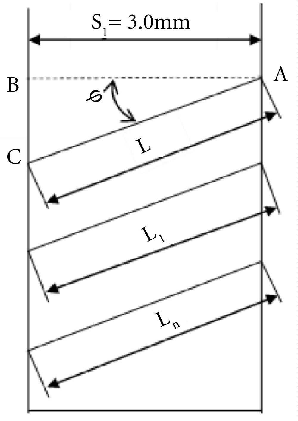
Figure 1: Scheme of the cutting edge of a disc mill for obtaining grooves.
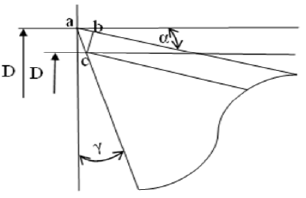
Figure 2: Scheme of the cutting edge of a disc mill for obtaining grooves.
Table 1 summarizes the weight loss in total during wear, as well as for individual teeth during sharpening. The table shows that wear on individual teeth occurs unevenly, since the loss of mass in almost every tooth varies. Based on (Table 1),
| Table 1: Showing weight loss measurements during sharpening of disc mill teeth. | |||||
| Weight of disc mills before sharpening (g) | Weight after wear, gr. | Difference after wear, mg | Total weight loss per operating cycle, mg | ||
| 101.91 | 101.82 | 0.09 | 0.61 | ||
| Tooth number, N | Weight after sharpening, gr. | Difference after sharpening, ∆, mg | Tooth number, N | Weight after sharpening, gr. | Difference after sharpening, ∆, mg |
| 1. | 101.79 | 0.03 | 13. | 101.53 | 0.03 |
| 2. | 101.76 | 0.03 | 14. | 101.50 | 0.01 |
| 3. | 101.74 | 0.02 | 15. | 101.49 | 0.03 |
| 4. | 101.73 | 0.01 | 16. | 101.46 | 0.02 |
| 5. | 101.72 | 0.01 | 17. | 101.44 | 0.01 |
| 6. | 101.70 | 0.02 | 18. | 101.43 | 0.02 |
| 7. | 101.68 | 0.03 | 19. | 101.41 | 0.01 |
| 8. | 101.65 | 0.01 | 20. | 101.40 | 0.04 |
| 9. | 101.64 | 0.02 | 21. | 101.36 | 0.03 |
| 10. | 101.62 | 0.02 | 22. | 101.33 | 0.02 |
| 11. | 101.60 | 0.04 | 23. | 101.31 | 0.01 |
| 12. | 101.56 | 0.03 | 24. | 101.30 | 0.01 |
| Note: “∆ = Difference in weight after sharpening (mg) | |||||
a Graph 1 of the weight loss of the teeth of a Disc mill with a diameter of 100 mm was compiled. The graph clearly indicates variability in wear across individual teeth occurs unevenly, since for some teeth the loss of mass, if a lot, means that the tooth experienced greater wear than others that had less mass loss. This suggests that in those teeth that had 0.01 mg of mass loss, wear did not occur at all, but since the mode of removing the processing share of 0.1 mm was adopted, all the teeth were sharpened.
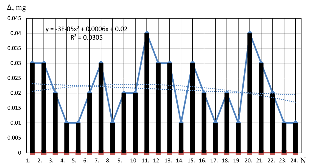
Graph 1: Graph of changing of the removed metal mass during teeth wear and sharpenning.
These wear patterns are consistent with findings from other studies in the field of woodworking tool performance. Trejo, et al. [1] examined circular saws used for high-density fiberboard cutting and identified progressive tooth wear that parallels the uneven wear observed in our disc mill tests. Their results showed that cutting force and heating patterns play a significant role in accelerating front-edge wear, which we also observed in our flank surfaces. Kang, et al. [2] analyzed polycrystalline diamond (PCD) blades in composite cutting and highlighted microfracture propagation and tooth chipping as dominant modes of damage—confirming that cutting tool geometry and impact zone are critical. Additionally, Javidani, et al. [4] reviewed tribological performance in wood-processing tools and concluded that abrasive and adhesive mechanisms dominate wear in thermally and mechanically stressed environments. Their findings support our observation that conventional sharpening protocols, while restoring edge geometry, may not fully mitigate material fatigue and surface degradation. Together, these studies reinforce the need to optimize sharpening intervals and tool material composition to enhance disc mill longevity in furniture production.
As a result of research, it was revealed that the length of the cutting edge of the teeth of Disc mills for producing grooves changes during the processing of wood materials and which contributes to cutting tool dulling.
Practical values obtained by calculating the size and shape of the teeth of a Disc mill show that wear on the front and rear surfaces occurs unevenly both over the surface and over individual teeth. However, standard sharpening modes are commonly used in production, which leads to rapid depletion of the cutting tool.
Taking these factors into account, it is important to give production new sharpening protocols to extend cutting tool life of the cutting tool for a longer time and at the same time improve the mechanical processing quality of wood materials, thereby enhancing the final quality of furniture products.
Data availability
All relevant data are included within the article.
We acknowledge HASANOGLU for technical support provided at the factory. https://www.hasan-oglu.az/; and to Baku Engineering University https://beu.edu.az/en for their collaboration with Azerbaijan Technical University.
- Trejo J, Polli ML, Da Rocha MP, Torres Á, Belini UL, Ninin P. Working limit of the circular saws in the cutting of high density fiberboard (HDF) through a nonlinear model and differential equations. Eur J Wood Prod. 2020;78:1183–1194. Available from: https://doi.org/10.1007/s00107-020-01596-9
- Kang J, Zhang H, Zhang Z, Bai T, Zuo C, Guo J, et al. Investigating damage mechanisms of honeycomb cores machined with PCD circular saw blades. J Mater Process Technol. 2024;327:118381. Available from: https://doi.org/10.1016/j.jmatprotec.2024.118381
- Sandak J, Orlowski K. Machine vision detection of the circular saw vibrations. J Mach Eng. 2018;18(3):67–77. Available from: http://dx.doi.org/10.5604/01.3001.0012.4617
- Javidani M, Heidari M, Jahazi M. Enhancing the tribological performance of tool steels for wood-processing applications: A comprehensive review. Metals. 2023;13(8):1460. Available from: https://doi.org/10.3390/met13081460
- Abbasov VA, Bashirov RJ. Features of ultrasound application in plasma-mechanical processing of parts made of hard-to-process materials. Metal Work Mater Sci. 2022;24(3):53-65. Available from: https://doi.org/10.17212/1994-6309-2022-24.3-53-65
- Licow R, Chuchala D, Deja M, Orlowski KA, Taube P. Effect of pine impregnation and feed speed on sound level and cutting power in wood sawing. J Clean Prod. 2020;272:122833. Available from: https://doi.org/10.1016/j.jclepro.2020.122833
- Al-Asadi MM, Al-Tameemi HA. A review of tribological properties and deposition methods for selected hard protective coatings. Tribol Int. 2022;176:107919. Available from: https://doi.org/10.1016/j.triboint.2022.107919
- Fanidi O, Kostryukov AA, Shchedrin AV, Ignatkin IYu. Comparison of analytical and experimental force in cylindrical workpiece drawing process. Tribol Ind. 2021;43(1):1–11. Available from: https://doi.org/10.24874/ti.1000.11.20.02
- Kubich V, Pavlenko D, Fasol Y, Syvachuk O. Comparison of high-temperature wear resistance of gas-flame and ion-plasma sealing coatings with 0.1% yttrium. Tribol Ind. 2024;46(3):486–498. Available from: https://doi.org/10.24874/ti.1587.11.23.03
- Kabaldin YG, Shatagin DA. Artificial intelligence and cyberphysical machining systems in digital production. Russ Eng Res. 2020;40:292–296. Available from: https://doi.org/10.3103/S1068798X20040115