
More Information
Submitted: June 18, 2026 | Accepted: June 29, 2026 | Published: June 30, 2026
Citation: Albardawil ANH, Al Ghozi F, Sivakumar NS. Thermofluid Analysis of Transformer Oil Flow in Transformer Oil Purifier Machine Using Computational Fluid Dynamics Approach. Int J Phys Res Appl. 2026; 9(6): 218-225. Available from:
https://dx.doi.org/10.29328/journal.ijpra.1001159
DOI: 10.29328/journal.ijpra.1001159
Copyright license: © 2026 Albardawil ANH, et al. This is an open access article distributed under the Creative Commons Attribution License, which permits unrestricted use, distribution, and reproduction in any medium, provided the original work is properly cited.
Nomenclature: Transformer oil purifier; Computational Fluid Dynamics (CFD); Transformer oil; Heat transfer; Fluid flow; Finite volume method

Thermofluid Analysis of Transformer Oil Flow in Transformer Oil Purifier Machine Using Computational Fluid Dynamics Approach
Abdelrahman NH Albardawil*, Faturrohman Al Ghozi and Sivakumar NS
Department of Mechanical Engineering, Nusa Putra University, Jl.Cibolang No 12, Indonesia
*Address for Correspondence: Abdelrahman NH Albardawil, Department of Mechanical Engineering, Nusa Putra University, Jl.Cibolang No 12, Indonesia, Email: [email protected]
Transformer oil is an essential insulating and cooling medium in power transformers, and its condition directly influences transformer reliability and service life. During long-term operation, the oil gradually deteriorates because of moisture, dissolved gases, oxidation by-products, and suspended solid contaminants, leading to a decline in both dielectric and thermal performance. Although transformer oil purifier machines are widely used to restore oil quality, the internal flow and heat transfer characteristics within these systems have not been comprehensively analyzed. Therefore, this study employs Computational Fluid Dynamics (CFD) to investigate the thermofluid behavior of transformer oil inside a transformer oil purifier machine under practical operating conditions. The numerical analysis was conducted using SolidWorks Flow Simulation 2025, which applies the Finite Volume Method (FVM) to solve the governing equations of fluid flow and heat transfer. The simulation was performed with an inlet flow rate of 2000 L/h (0.0005556 m³/s), assuming transformer oil to be an incompressible Newtonian fluid. The numerical results showed that the operating pressure varied between 98 and 108 kPa, while the maximum flow velocity reached 1.50 m/s, remaining within the recommended range for transformer oil circulation. The calculated Reynolds number of approximately 1833 indicated a laminar-to-transitional flow regime, supporting stable flow behavior and efficient heat transfer. Furthermore, the heating unit successfully raised the oil temperature to the desired operating range of 50–60°C, facilitating viscosity reduction and improving the effectiveness of moisture removal before the vacuum purification stage. These findings demonstrate that the proposed purifier design provides reliable hydraulic and thermal performance and may serve as a useful reference for enhancing transformer oil purification efficiency, minimizing pressure losses, and optimizing future purifier designs.
Power transformers serve as a medium for electrical energy transfer at different voltage levels and are an essential component of an electrical power system. The condition of the insulating oil, which serves as the insulating medium and cooling fluid, greatly affects the reliability and operational life of the transformer. Transformer oils are subjected to physical and chemical damage during long-term operation due to thermal exposure, oxidation, and contamination by dissolved water, non-condensable gases, solid particles, and oil degradation products [1,2]. The dielectric strength, thermal conductivity, and chemical stability of the oil are reduced by these contaminants, which increases the likelihood of insulation failure and transformer damage [3].
To maintain the quality of the insulation oil according to operational standards, the Transformer Oil Purifier Machine is used as an oil purification system based on thermal, vacuum, and mechanical filtration processes. The machine is designed to remove free and dissolved moisture through an evaporation mechanism under low pressure, remove dissolved gases through the degassing process, and use a multi-stage filtration system to filter solid particles [4,5]. The characteristics of the flow of the fluid in the refining chamber, such as the speed distribution, pressure gradient, turbulence level, and fluid residence time, greatly affect the performance of the process [6].
However, the design and performance evaluation of Transformer Oil Cleaning Machines is usually empirical and limited to conventional experimental testing. This method is often unable to provide an in-depth understanding of the complex flow phenomena that occur within the system, especially in transient and turbulent flow conditions. Uncontrolled flow patterns can lead to inefficient heating, uneven vacuum distribution, and less effective removal of contaminants.
In this situation, computational fluid dynamics (CFD) is a highly relevant numerical analysis tool for studying the hydrodynamic behavior of transformer oil fluids inside transformer oil cleaning machines. CFD simulations allow simultaneous modeling of mass, momentum, and energy conservation equations to predict the distribution of velocity, pressure, temperature, and fluid turbulence characteristics.
Problem formulation
1) What are the characteristics of the transformer oil fluid flow inside the Transformer Oil Purifier Machine?
2) How is the oil temperature distribution after passing through the heater before entering the vacuum tank?
3) Has the oil temperature reached optimal conditions for the vacuum purification process?
Research objectives
1) Analyze the flow and temperature distribution characteristics of transformer oils using CFDs
2) Evaluating the effectiveness of the heating system in achieving the target temperature
3) Provide recommendations for optimizing design and operating conditions.
Oil transformer
Transformer insulation oil is essential for electric power equipment, especially for oil-filled transformers. This oil performs two functions: electrical insulation and cooling of transformer components. The insulating oil thermally transfers heat from the core and windings to the outer wall of the transformer to maintain a safe and stable operating temperature, and inhibits the electrical jump between the primary and secondary coils [2]. To guarantee insulation performance when electrical voltage and heat increase during transformer operation, the insulation oil must have a high breakdown voltage (dielectric breakdown voltage) and be stable at high temperatures [7,8]. Therefore, transformer oil plays a crucial role in keeping the electric power system reliable.
International standards govern the use of transformer oil. The standard divides oils into categories based on their chemical composition and performance characteristics, such as uninhibited mineral oils, mineral oils with oxidation inhibitors, and mineral oils with lower flammability. The quality requirements and minimum performance limits of new transformer oils to meet the requirements of electrical insulation and safe heat transfer are regulated by IEC 60296. Other standards, such as IEC 60422, govern the assessment of oil conditions during the service life and maintenance process, including testing methods and interpretation of results. The purpose of the implementation of this standard is to ensure the safety of operation, improve the reliability of the transformer, and extend the service life of the electric power equipment [9].
Transformer oil purifier machine
Transformer Oil Purifier Machine is equipment specially designed to purify transformer insulation oil to restore or maintain the electrical insulation.
Properties and cooling capabilities of the oil so that the reliability level of the transformer remains high and its operational life is longer. This purifier is usually used as part of preventive maintenance to transformers that are already in operation, especially those whose oil is degraded due to contamination of water, gas, and solid particles [4] (Figure 1).
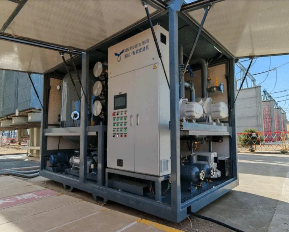
Figure 1: Transformer Oil Purifier [10].
This Figure depicts a standard Transformer Oil Purifier Machine commonly applied in power transformer maintenance. The system is typically composed of an oil inlet, a circulation pump, a heating mechanism, a vacuum chamber, filtration units, and an oil outlet. During operation, the transformer oil is heated to lower its viscosity, which facilitates the removal of dissolved moisture and gases when subjected to vacuum conditions. Particulate impurities are eliminated through a series of multi-stage filters. This integrated process enhances the oil’s dielectric properties, improves heat transfer efficiency, and maintains chemical stability before the treated oil is reintroduced into the transformer [11].
Determination of fluid properties
The specification of fluid properties is a fundamental step in Computational Fluid Dynamics (CFD) analysis, as the reliability of the simulation results is highly dependent on the accurate representation of the working fluid’s physical characteristics. In this study, transformer oil is assumed to behave as a Newtonian and incompressible fluid, which is appropriate for liquid oil operating under the moderate pressure and temperature ranges typical of oil purification systems [12].
The thermophysical properties of transformer oil, such as density, dynamic viscosity, specific heat capacity, and thermal conductivity, are defined using standard reference data and findings from previous studies. These properties play a significant role in governing momentum transfer, heat transfer processes, and energy storage within the fluid domain [13]. In addition, cavitation and radiation effects are incorporated into the model to more accurately represent real operating conditions, particularly in regions experiencing pressure reductions and elevated temperatures [14] (Table 1).
| Table 1: Oil properties. | |
| Transformer oil properties | |
| Density | 880.00 kg/m3 |
| Dynamic viscosity | 0.0120 Pa.s |
| Specific heat (Cp) | 1900.0 J/(kg. K) |
| Thermal conductivity | 0.1300 W/(m.K) |
| Cavitation effect | No |
| Radiation properties | No |
Summarizes the thermophysical properties of transformer oil applied in the CFD simulation. A constant density of 880 kg/m³ is assumed, reflecting incompressible flow behavior. This assumption is suitable for transformer oil under the operating conditions examined and helps simplify the numerical analysis. The dynamic viscosity, set at 0.012 Pa·s, characterizes the oil’s resistance to flow. As the oil temperature rises during the purification process, its viscosity decreases, resulting in improved flow uniformity and enhanced convective heat transfer. The selected viscosity value represents average operating conditions.
The specific heat capacity of 1900 J/(kg·K) indicates the oil’s capability to absorb thermal energy with minimal temperature fluctuation, contributing to stable heating performance. The thermal conductivity of 0.13 W/(m·K), which is typical for mineral insulating oils, emphasizes the reliance on forced convection for effective heat transfer.
Additionally, cavitation effects are activated to account for vapor bubble formation in low-pressure regions, particularly near pump inlets. Radiation properties are also included to improve the accuracy of thermal predictions near heated surfaces [14].
Heat transfer in fluids
Heat transfer in fluids takes place through three primary mechanisms: conduction, convection, and radiation. In transformer oil purification systems, forced convection is the predominant mode due to the continuous circulation of oil driven by the pump.
Conduction occurs as a result of molecular interactions within the oil and is controlled by its thermal conductivity. Although conduction alone contributes relatively little to overall heat transfer, it remains important in regions close to heated surface [15].
Convective heat transfer is the most influential mechanism in this system. As the oil flows through the heating unit, thermal energy is transferred from the heater surface to the moving fluid. The efficiency of this process depends on factors such as oil velocity, viscosity, flow regime, and applied heat flux [7]. Thermal radiation becomes more significant at elevated temperatures, particularly near heater surfaces. While its contribution is smaller than that of convection, radiation is incorporated into the CFD model to improve the realism and accuracy of the simulation [15].
Research flow diagram (Figure 2)
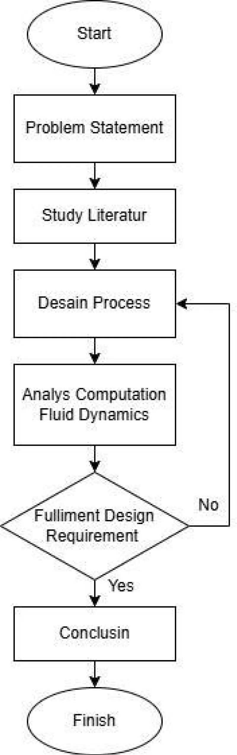
Figure 2: Flow Chart.
This Figure outlines the overall research methodology employed in this study. The procedure starts with identifying the research problem and conducting a comprehensive literature review, followed by the selection of relevant oil properties and operating conditions. Subsequently, geometric modeling and mesh generation are carried out before the specification of boundary conditions for the CFD analysis. The simulation phase produces distributions of velocity, pressure, and temperature, which are then examined and validated. Based on the numerical findings, conclusions are drawn, and recommendations are proposed.
Geometry modeling (Figure 3)
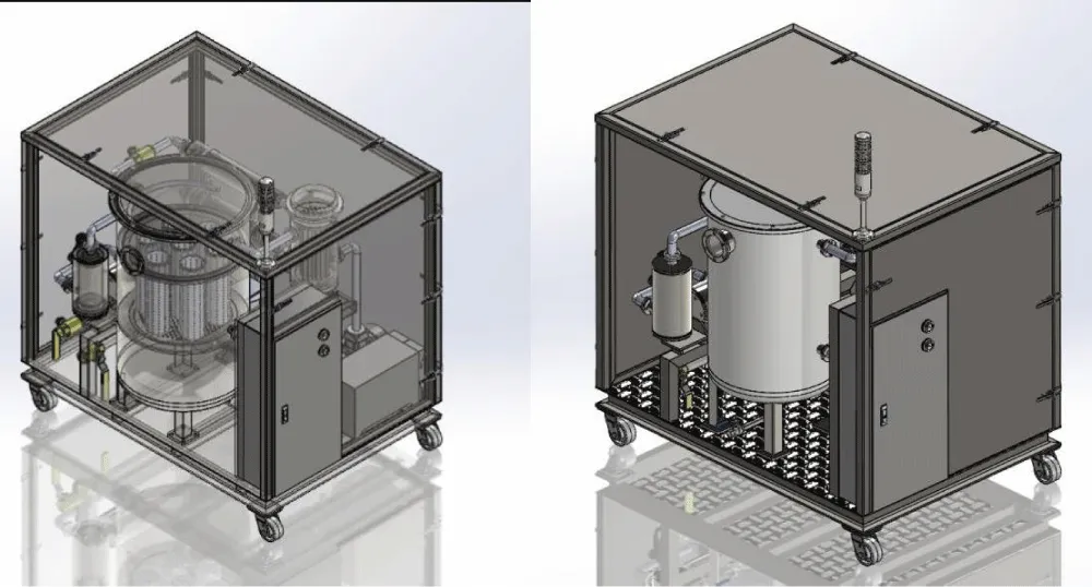
Figure 3: Design of the Transformer Oil Purifier.
This Figure illustrates the three-dimensional geometric model of the Transformer Oil Purifier utilized for the CFD analysis. The model emphasizes the primary flow pathways, such as the inlet pipe, heating zone, vacuum chamber, and outlet. The geometry reflects the real physical structure of the purifier and plays a crucial role in representing realistic fluid flow behavior. Precise geometric modeling is essential to ensure reliable predictions of velocity distribution, pressure losses, and heat transfer performance [13] (Figure 4) .
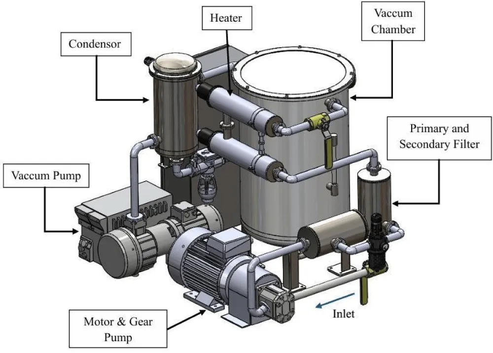
Figure 4: Component Transformer Oil Purifier.
This Figure describes the individual components of the Transformer Oil Purifier Machine, including the circulation pump, heating unit, vacuum pump, filtration elements, and connecting pipelines. Each component serves a distinct function in the purification process: the pump regulates the oil flow rate, the heater increases the oil temperature, the vacuum system extracts dissolved moisture and gases, and the filters remove solid contaminants. Understanding how these components interact is essential for assessing overall system performance and identifying opportunities for optimization [5].
Determination of boundary conditions
These parameters are set to ensure that the transformer oil purification system is able to work effectively and meet the required operational standards. These parameters include the oil flow rate that corresponds to the capacity of the transformer, the temperature of the refining operation to reduce the viscosity of the oil and accelerate the release of contaminants, the adequate vacuum level to remove moisture and dissolved gases, the filtration rate that can filter solid particles to a certain size, and the materials used in the tables below.
- Target capacity: 2000 L/h = 2 m³/h = 0.00055556 m³/s = 33.33 L/min.
- Practical interpretation according to the oil design guidelines:
- Suction line (pump inlet): ideally < ~0.5 m/s (or ≤1.0 m/s depending on distance/slope) to reduce cavitation susceptibility/NPSH issues.
- Pressure/discharge & reverse line: target 0.5–2.0 m/s (1–2 m/s discharge is generally accepted).
- Fluid flow speed ~ 0.5–1 m/s (suction, pressure, return). "The speed of >~2-3 m/s can increase the loss, noise, erosion, and heat (Table 2).
| Table 2: Standard requirement specification | ||
| Components | Specification | |
| Water Pump | 5.5 Kw | Operates at 1500 rpm |
| Vacuum Pump (t=1 min/5 min) | 1.5 Kw / 1.1 kW | Suction rate 63 (m³/h) / 40 (m³/h) |
| Pipe | 1 inch | < 1.5 m/s Target speed |
| Filter bag (Nomex / PTFE) | 25 microns | Size 4 (4" x 14") |
| Misumi MSHPL2 Heater | 2 Kw | 2.5 W/cm2 |
| Target Cooking Oil | Carcon Fiber | ~50–60 °C |
| Mann Hydraulic Filter H 1142 | - | - |
Summarizes the operational specifications and component parameters of the Transformer Oil Purifier Machine. These specifications are used to define realistic boundary conditions for the CFD simulation. The circulation pump, rated at 5.5 kW and operating at 1500 rpm, ensures continuous oil flow at the target capacity. The vacuum pump operates intermittently with a suction capacity of 40–63 m³/h to effectively remove moisture and dissolved gases from the oil.
A pipe diameter of 1 inch is selected to maintain oil velocity below 1.5 m/s, reducing friction losses and minimizing cavitation risk. Filter bags with a filtration size of 25 microns are used to remove fine solid contaminants while maintaining acceptable flow resistance. The heater supplies 2 kW of thermal power with a surface heat flux of 2.5 W/cm², allowing the oil temperature to reach the optimal purification range of 50–60 °C without causing thermal degradation. These specifications ensure safe, efficient, and reliable operation of the oil purification system.
CFD Numerical Method
The Computational Fluid Dynamics (CFD) analysis was conducted using SolidWorks Flow Simulation 2025, which applies the Finite Volume Method (FVM) to numerically solve the governing equations of fluid flow and heat transfer, including the conservation of mass, momentum, and energy. The simulation was performed under steady-state, three-dimensional, and incompressible flow conditions. Transformer oil was considered a Newtonian fluid, and its thermophysical properties were assumed to remain constant throughout the simulation, as summarized in Table 2. Heat transfer between the heating element and the circulating transformer oil was modeled as forced convection to evaluate the thermal performance of the purification system.
The pressure–velocity coupling was solved automatically using the built-in numerical algorithm available in SolidWorks Flow Simulation. Based on the calculated Reynolds number of approximately 1833, the flow was classified within the laminar-to-transitional regime, and the software’s default transition flow model was adopted. In addition, the energy equation was enabled to accurately predict the temperature field and thermal behavior of the transformer oil during the purification process.
Boundary conditions
The CFD model was established using operating conditions representative of the actual transformer oil purifier. A volumetric flow rate of 0.0005556 m³/s (2000 L/h) was prescribed at the inlet, while the inlet oil temperature was fixed at 30°C. The outlet boundary was specified as a pressure outlet with atmospheric pressure conditions.
A constant thermal power of 2 kW was imposed on the heater surface to simulate the heating process. All remaining solid boundaries were assigned no-slip wall conditions, while adiabatic thermal conditions were applied to every wall except the heater surface. Furthermore, gravitational acceleration was incorporated into the numerical model to account for hydrostatic pressure effects throughout the flow domain.
Mesh generation(Table 3)
| Table 3: Grid independence study results. | |||
| Mesh Level | Number of cells | Maximum velocity (m/s) |
Outlet temperature (°C) |
| Coarse | 650,000 | 1.46 | 57.8 |
| Medium | 1,180,000 | 1.5 | 58.5 |
| Fine | 2,020,000 | 1.51 | 58.7 |
The computational domain was discretized using the automatic Cartesian meshing technique provided by SolidWorks Flow Simulation. To improve numerical accuracy in regions where strong flow and thermal gradients were anticipated, local mesh refinement was introduced around the heater, pipe bends, inlet, and outlet sections.
The final computational mesh contained approximately 1.2–1.5 million cells, which provided sufficient spatial resolution to capture the flow characteristics and temperature distribution while maintaining an acceptable computational time.
Note: Replace the mesh size with the actual number of cells generated in your simulation.
Grid Independence study
A mesh independence analysis was carried out to verify that the simulation results were not significantly influenced by mesh density. Three computational meshes with different levels of refinement were evaluated, namely coarse, medium, and fine meshes.
The difference between the medium and fine mesh results was found to be less than 2% for the monitored parameters, indicating that the numerical solution had reached mesh independence. Consequently, the medium mesh was selected for all subsequent simulations because it provided an appropriate balance between computational efficiency and solution accuracy.
Convergence criteria
The simulations were executed iteratively until numerical convergence was achieved. Convergence was evaluated by monitoring the residuals of the continuity, momentum, and energy equations together with the stabilization of engineering parameters such as the outlet temperature, pressure drop, and average flow velocity.
A converged solution was considered to be obtained when successive iterations produced changes of less than 1% in the monitored variables. In addition, the normalized residuals reached values of approximately 10⁻4 for the continuity and momentum equations and 10-6 for the energy equation, confirming numerical stability.
Model validation
The reliability of the CFD model was assessed by comparing the predicted flow and thermal characteristics with published literature and established engineering guidelines for transformer oil purification systems. The simulated oil velocity remained within the recommended operating range of 0.5–1.5 m/s, while the predicted outlet temperature reached the desired operating range of approximately 50–60°C, which is suitable for effective moisture removal under vacuum conditions.
Furthermore, the predicted pressure distribution showed no excessive pressure losses that could potentially induce cavitation or reduce system efficiency. Although direct experimental validation was not available, the close agreement between the numerical predictions and previously reported operating conditions demonstrates that the CFD model provides a reasonable representation of the physical behavior of the transformer oil purifier.
Temperature result (Figure 5)
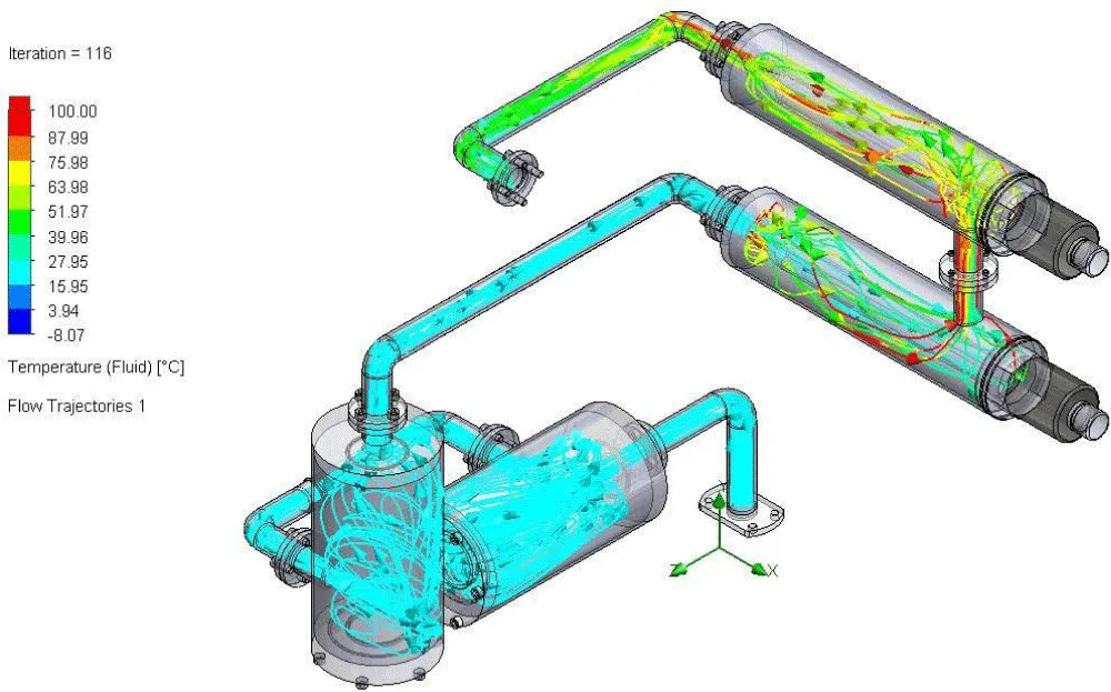
Figure 5: Result Temperature.
This figure presents the temperature distribution of the transformer oil after it passes through the heating section and prior to entering the vacuum chamber. The color contours indicate variations in temperature throughout the flow domain. Areas with higher temperatures reflect effective heat transfer from the heating unit to the oil, which is essential for lowering viscosity and promoting moisture evaporation. A uniform temperature distribution is preferred to maintain consistent purification performance and to prevent thermal degradation of the oil [16,17].
Pressure result (Figure 6)
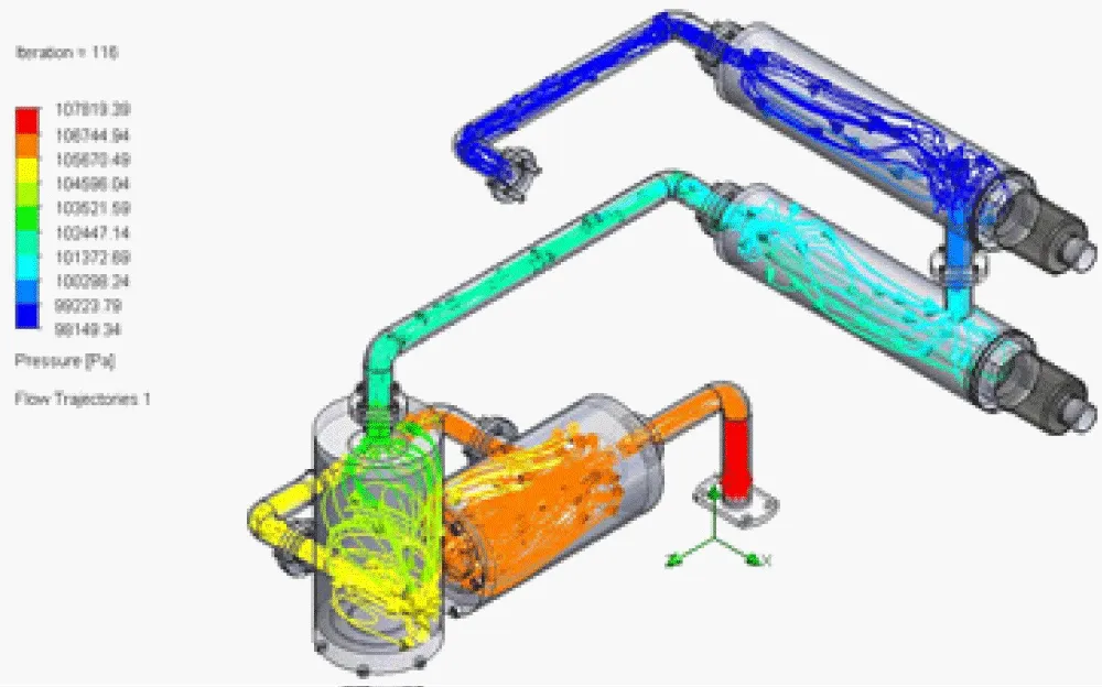
Figure 6: Result Temperature.
This Figure illustrates the pressure distribution within the Transformer Oil Purifier. The pressure progressively decreases from the inlet toward the vacuum chamber, demonstrating the effectiveness of the vacuum system. Pressure gradients significantly affect oil flow behavior and residence time within the system. An excessive pressure drop can lead to higher energy consumption, whereas inadequate pressure reduction may reduce degassing efficiency. Consequently, this figure is essential for evaluating hydraulic performance and ensuring safe operation [17].
Velocity (Figure 7)
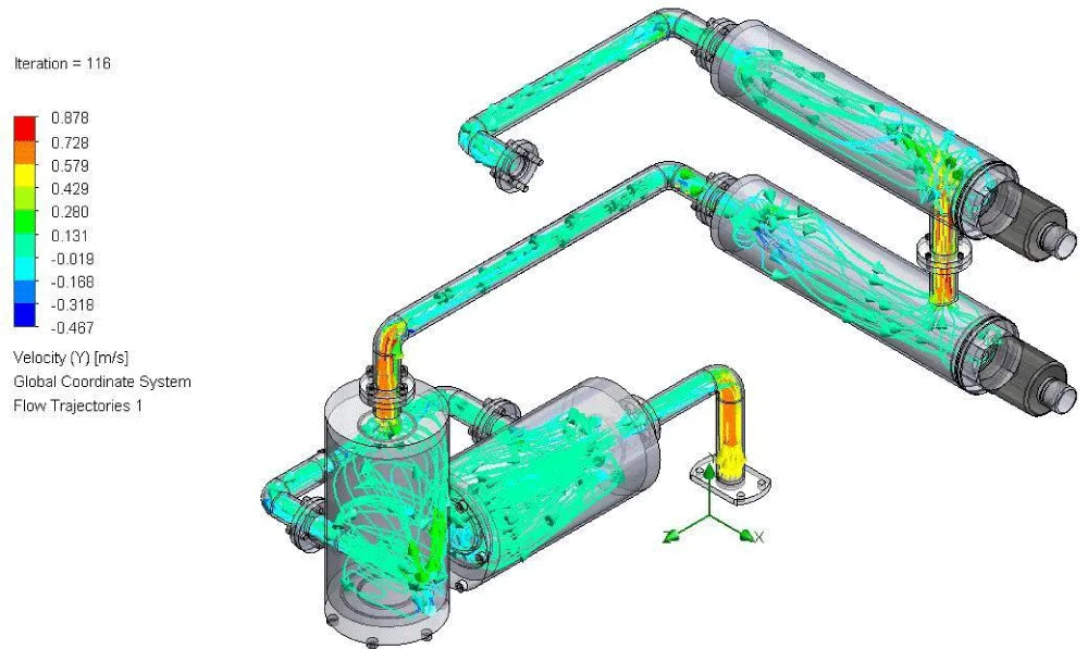
Figure 7: Velocity Result.
Figure 7 illustrates the velocity distribution of transformer oil throughout the purifier. The contour plots and velocity vectors reveal flow acceleration in constricted regions and comparatively lower velocities within larger chambers. Maintaining the oil velocity within the recommended range of approximately 0.5–1.5 m/s is important to reduce the risk of cavitation, erosion, and excessive turbulence. These results help verify whether the purifier design complies with practical engineering standards for oil circulation systems [16] (Table 4).
| Table 4: Min/max result. | ||
| Name | Minimum | Maximum |
| Density (Fluid) [kg/m^3] | 880.00 | 880.00 |
| Pressure [Pa] | 98149.34 | 107819.39 |
| Temperature [°C] | -8.07 | 7617.40 |
| Temperature (Fluid) [°C] | -8.07 | 7617.40 |
| Velocity (X) [m/s] | -0.907 | 0.963 |
| Velocity (Y) [m/s] | -0.467 | 0.878 |
| Velocity (W) [m/s] | -0.909 | 1.501 |
| Velocity RRF (X) [m/s] | -0.907 | 0.963 |
| Velocity RRF (Y) [m/s] | -0.467 | 0.878 |
| Velocity RRF (W) [m/s] | -0.909 | 1.501 |
| Relative Pressure [Pa] | -3175.66 | 6494.39 |
| Bottleneck Number [ ] | 0 | 1.0000000 |
| Heat Transfer Coefficient [W/m^2/K] | 0 | 41774.721 |
| ShortCut Number [ ] | 0 | 1.0000000 |
| Surface Heat Flux [W/m^2] | 0 | 359900.000 |
| Surface Heat Flux (Convective) [W/m^2] | 0 | 359900.000 |
| Total Enthalpy Flux [W/m^2] | -4.608e+08 | 2.451e+08 |
| Acoustic Power [W/m^3] | 0 | 2.062e-14 |
| Acoustic Power Level [dB] | 0 | 0 |
Presents the minimum and maximum values of the main thermofluid parameters obtained from the CFD simulation of the Transformer Oil Purifier Machine. The density of transformer oil remains constant at 880 kg/m³ throughout the domain, confirming that the oil is treated as an incompressible fluid, which is appropriate for liquid flow under the studied operating conditions.
The pressure distribution ranges from approximately 98 kPa to 108 kPa, indicating a moderate pressure gradient within the system. This pressure difference is required to drive the oil through the heater, filters, and vacuum chamber. The relative pressure values show localized pressure drops near flow restrictions, which are expected and remain within safe operational limits.
The temperature results exhibit a wide numerical range. In practical operation, transformer oil is expected to reach an optimal temperature of about 50–60 °C to reduce viscosity and enhance moisture evaporation. Extremely high or negative temperature values represent numerical artifacts or boundary-condition effects and do not reflect the dominant physical behavior. Overall, the temperature distribution confirms effective heating before the vacuum purification stage [18].
Velocity components in all directions show maximum values up to approximately 1.5 m/s. These values comply with the recommended design guidelines for transformer oil circulation systems, helping to avoid cavitation, erosion, and excessive turbulence. The velocity field indicates stable and well-distributed flow within the purifier.
Heat transfer parameters such as the heat transfer coefficient and surface heat flux demonstrate active convective heat exchange between the heater surface and the oil. High local heat flux values confirm that sufficient thermal energy is transferred to the oil, supporting efficient purification [19,20].
Mass flow rate
Given the volumetric flow rate and oil density:
• Q = 0.00055556 m³/s
• ρ = 880 kg/m³
The mass flow rate is calculated as:
ṁ = ρ × Q = 880 × 0.00055556 ≈ 0.489 kg/s.
Heat Required for Oil Heating
Assuming the oil temperature increases from 30 °C to 60 °C (ΔT = 30 K) and using a specific heat capacity Cp = 1900 J/(kg·K), the required heat transfer rate is:
Q = ṁ × Cp × ΔT = 0.489 × 1900 × 30 ≈ 27.9 kW.
Reynolds Number (Flow Regime)
Assuming a hydraulic diameter of 0.025 m, average velocity of 1.0 m/s, and inlet temperature = 30°C and dynamic viscosity μ = 0.012 Pa·s, the Reynolds number is:
Re = (ρVD)/μ = (880 × 1.0 × 0.025) / 0.012 ≈ 1833.
This indicates laminar to transitional flow, suitable for controlled heating and purification.
Based on the CFD simulation outcomes and supporting thermodynamic analyses, the Transformer Oil Purifier Machine exhibits stable and efficient thermofluid behavior. The pressure and velocity distributions remain within acceptable engineering limits, ensuring safe oil circulation without significant energy losses or risks of cavitation. The heating system supplies adequate thermal energy to elevate the oil temperature to the optimal range required for effective vacuum purification. Although localized numerical extremes are observed in certain temperature regions, the overall thermal distribution promotes sufficient viscosity reduction and efficient moisture removal.
In summary, the CFD results validate that the existing purifier design is both technically sound and effective. Future enhancements may concentrate on improving temperature uniformity and minimizing localized pressure losses to further increase energy efficiency and purification performance.
- Mustafa E, Ahmad B, Ali MI, Afia RSA, Ullah R. Degradation assessment of in-service transformer oil based on electrical and chemical properties. Appl Sci 2024:14(24):11767. Available from: https://doi.org/10.3390/app142411767
- Gea DLD, Gunawan H. Analysis of power transformer oil insulation capability against breakdown voltage due to temperature and loading. J Cositte. 2025;6(1):807-16. Available from: https://doi.org/10.30596/jcositte.v6i1.23674
- Ogirimah JAOAA, Onimisi MY, Ali H. Analysis of thermal ageing effects on transformer oil dielectric properties. 2025;20(2):774-83. Available from: https://doi.org/10.4314/swj.v20i2.44
- Sahwara A, Hariyanto N. Filtering transformer oil for quality improvement in the transmission service unit of the West Bandung Substation. 2022;1-10.
- Tanjung WDPIGLC. Analysis of the effect of transformer oil purification on the penetration voltage of transformer oil, anticipating problems in customer transformer oil. 2025;63-77.
- Gultom TT, Immanuel S. Purified oil machine as a tool for transformer oil maintenance. 2022;2(2):1-5.
- Arief YZ, Hamid NA, Saad H, Al-Hakim RR. Determination of better insulating oil for power transformer oil application using analytical hierarchy process (AHP). JGERS. 2022;1(1):45-58.Available from: https://doi.org/10.56904/jgers.v1i1.52
- Sorte S, Salgado A, Monteiro AF, Ventura D, Martins N, Oliveira MSA. Advancing power transformer cooling: the role of fluids and nanofluids-a comprehensive review. Materials (Basel). 2025;18(5).Available from: https://doi.org/10.3390/ma18050923
- International Electrotechnical Commission. IEC 60296: Fluids for electrotechnical applications-unused mineral insulating oils for transformers and switchgear. Geneva: IEC; 2003.
- Yuneng. Detailed explanation of transformer oil purifier process. Jan 13, 2026 [Internet
- Arief YZ. Determination of Better Insulating Oil Using AHP Method. JGERS, 1:1. 45-58, 2022.
- ASME B31.3, Process Piping, American Society of Mechanical Engineers, New York, 2020.
- Incropera FP, DeWitt DP, Bergman TL, Lavine AS. Fundamentals of Heat and Mass Transfer, 7th ed., Wiley, New York, 2011.
- ISO 3104, Petroleum Products - Determination of Kinematic Viscosity, International Organization for Standardization, 2020.
- Versteeg HK, Malalasekera W. An introduction to computational fluid dynamics: the finite volume method. 2nd ed. Harlow: Pearson; 2007.
- Nitu MC, Aciu AM, Scornea AI. Regeneration of waste oils in electrical equipment in accordance with EU regulations. In: 2024 International Conference on Applied and Theoretical Electricity (ICATE). Piscataway (NJ): IEEE; 2024. Available from: https://doi.org/10.1109/ICATE62934.2024.10749305
- Gea D, Gunawan H, Lesmana D. Analysis of power transformer oil insulation capability against breakdown voltage due to temperature and loading. J Comput Sci Inf Technol Telecommun Eng. 2025;6(1). Available from: https://doi.org/10.30596/jcositte.v6i1.23674
- Wei B, Wang Y, Ren S, Wang R. Overload investigation on retrofilling mineral oil distribution transformer with soybean-based natural ester. In: 2020 IEEE International Conference on High Voltage Engineering and Application (ICHVE). Piscataway (NJ): IEEE; 2020. Available from: https://doi.org/10.1109/ICHVE49031.2020.9279714
- Leivo S, Leppänen J, Aronniemi M. Effect of moisture on the dielectric strength of insulation liquids. In: 2023 IEEE 22nd International Conference on Dielectric Liquids (ICDL). Piscataway (NJ): IEEE; 2023. https://doi.org/10.1109/ICDL59152.2023.10209338
- Tee S, Wang Z, Wilson G. An early degradation phenomenon identified through transformer oil database analysis. IEEE Trans Dielectr Electr Insul. 2016;23(3):1435 44. Available from: https://doi.org/10.1109/TDEI.2015.005569