
More Information
Submitted: April 09, 2025 | Approved: April 28, 2025 | Published: May 01, 2025
How to cite this article: Baranov SA. Natural Ferromagnetic Resonance in Cast Glass -coated Amorphous Magnetic Micro - and Nanowires and its Applications for Non-contact Diagnostics. Int J Phys Res Appl. 2025; 8(5): 106-115. Available from:
https://dx.doi.org/10.29328/journal.ijpra.1001119
DOI: 10.29328/journal.ijpra.1001119
Copyright license: © 2025 Baranov SA. This is an open access article distributed under the Creative Commons Attribution License, which permits unrestricted use, distribution, and reproduction in any medium, provided the original work is properly cited.
Keywords: Cast glass-coated amorphous magnetic micro - and nanowires; Magnetostriction; Magnetoelastic anisotropy; Natural ferromagnetic resonance; Stress effect

Natural Ferromagnetic Resonance in Cast Glass -coated Amorphous Magnetic Micro - and Nanowires and its Applications for Non-contact Diagnostics
Serghei A Baranov1,2*
1Moldova State University, Institute of Applied Physics, 5 Academiei st., Chisinau MD-2028, Republic of Moldova
2Shevchenko Pridnestrov’e State University, str. 25 Oktyabrya 128, Tiraspol, Republic of Moldova
*Address for Correspondence: Serghei A Baranov, Moldova State University, Institute of Applied Physics, 5 Academiei st., Chisinau MD-2028, Republic of Moldova, Email: [email protected]; [email protected]
The Natural Ferromagnetic Resonance (NFMR) in cast glass-coated amorphous magnetic microwires has been studied theoretically and experimentally. The Natural Ferromagnetic Resonance (NFMR) reveals large residual stresses appearing in the microwire core in the course of casting. These stresses, together with the magnetostriction, determine the magnetoelastic anisotropy. Besides residual stresses, the NFMR frequency is influenced by externally applied stresses on the microwire or the composite containing the so-called stress effect (SE).
The paper analyzes technological aspects of the Taylor-Ulitovsky method used to produce cast glass-coated amorphous magnetic micro- and nanowires.
The dependence of the NFMR frequency on the deformation of the microwires is proposed to be used in the remote diagnostics of critical infrastructure deformations and for remote diagnostics in medicine.
The properties of the magnetic glass-coated cast amorphous micro and nanowires (GCAMNWs) studies in many publications by various research groups [1-20]. The phenomenon of Natural Ferromagnetic Resonance (NFMR) in CGCMMWs [4,6-13] is extremely interesting from the viewpoint of using it for non-contact diagnostics of distant objects. The diagnostics become possible due to the stress effect on the NFMR, that is, the shift of the resonance frequency as a result of a deformation of the object. Such a frequency shift can be measured by irradiating the object with microwaves emitted by radar at frequencies near the NFMR and detecting the reflected signal, thus revealing a deviation of the resonance frequency from the original value.
One of the dangerous consequences of terrorist acts is a traumatism of the people owing to glasses shattering of windows of administration, industrial and apartment houses, Therefore actual problem is the strength improvement of a glass, reducing the probability of formation and spread of debris during shattering.
Also modern terrorist acts are possible with use of concentrated beams of radio-frequency pulses with the purpose of disable computers and other electronic devices, running life-support systems of cities etc.
Besides the radio-electronic intelligence service using directional electromagnetic radiation for reading, for example via window opening, information typed on the keyboard of computer, located in the monitor etc. have to do with modern terrorist acts and espionage activity.
It is known that the usual glass practically completely passes electromagnetic radiation in all diapason of frequencies. Therefore problem of making radio-screening glasses also is actual.
The delivered problems can be decided in a complex with applying glasses containing microwires in a glass shell obtained by a method of casting from a solution phase on a method Taylor-Ulitovskiy.
Reinforcing glass with microwires encased in a glass shell and bonded with an adhesive film enhances its durability under impact and static loads. Additionally, in the event of glass breakage, it prevents the scattering of debris.
Moreover, these glasses significantly diminish the transmission of electromagnetic radiation across a broad frequency range, spanning from hundreds of MHz to tens of GHz.
Armoring of glasses by a microwire does not reduce the ability of passing of light in all gamut of colors, as the usual glass and does not change a view of a glass more worse. The microwire in glass practically is imperceptible.
Other possible applying of a microwire in the antiterrorist purposes also for making hardening and screening of effect it possibility to armor by a microwire elements Kevlar vests, helmets, made from plastic such as Kevlar.
The microwire represents a construction containing continuous metal core coated with a continuous glass shell. For a more precise comparison of the theory with the experiment a series of the experimental measurements is needed, which are also discussed in the paper.
The resulting microwires of optimal chemical composition were tested for reinforcing window glass in medical buildings. A mesh of high-strength microwire was preliminarily created using linear and orthogonal winding. Then, a melt was poured into special molds to reinforce window glass to obtain a sheet blank with a thickness of about 1-3 mm.
A simple production technology of cast glass-coated amorphous micro- and nanowires (CGCAMWs) was first introduced in 1924 by Taylor [1-4]. The principle of this method lays in the heating of a metal sample inside a horizontally positioned glass tube with a gas burner till the softening of the tube and the melting of the metal followed by rapid stretching of the tube. This method did not receive wide acceptance, as it produced microwires of limited lengths and their parameters were uncontrollable.
Later, in the period 1948 – 1957, this method was significantly modified by Ulitovsky. The essence of this method is that a continuous liquid metal filling the capillary is drawn out from a vertically positioned glass tube (Figure 1A). Modified Taylor–Ulitovsky method allows producing large amounts of such microwires. Interest in the cast glass-coated microwires has greatly increased over the last few years, mainly due to their technological applications, in particular, as sensor elements in various devices. Consequently, preparation of CGCFMWs by the Taylor-Ulitovsky method and the study of their magnetic properties were reported in many my publications and publications by various research groups [1-7]. It is essential that the microwires are manufactured using a rapid solidification technique. However, the main peculiarity of the aforementioned microwires is the simultaneous rapid solidification of metallic alloy covered by glass.
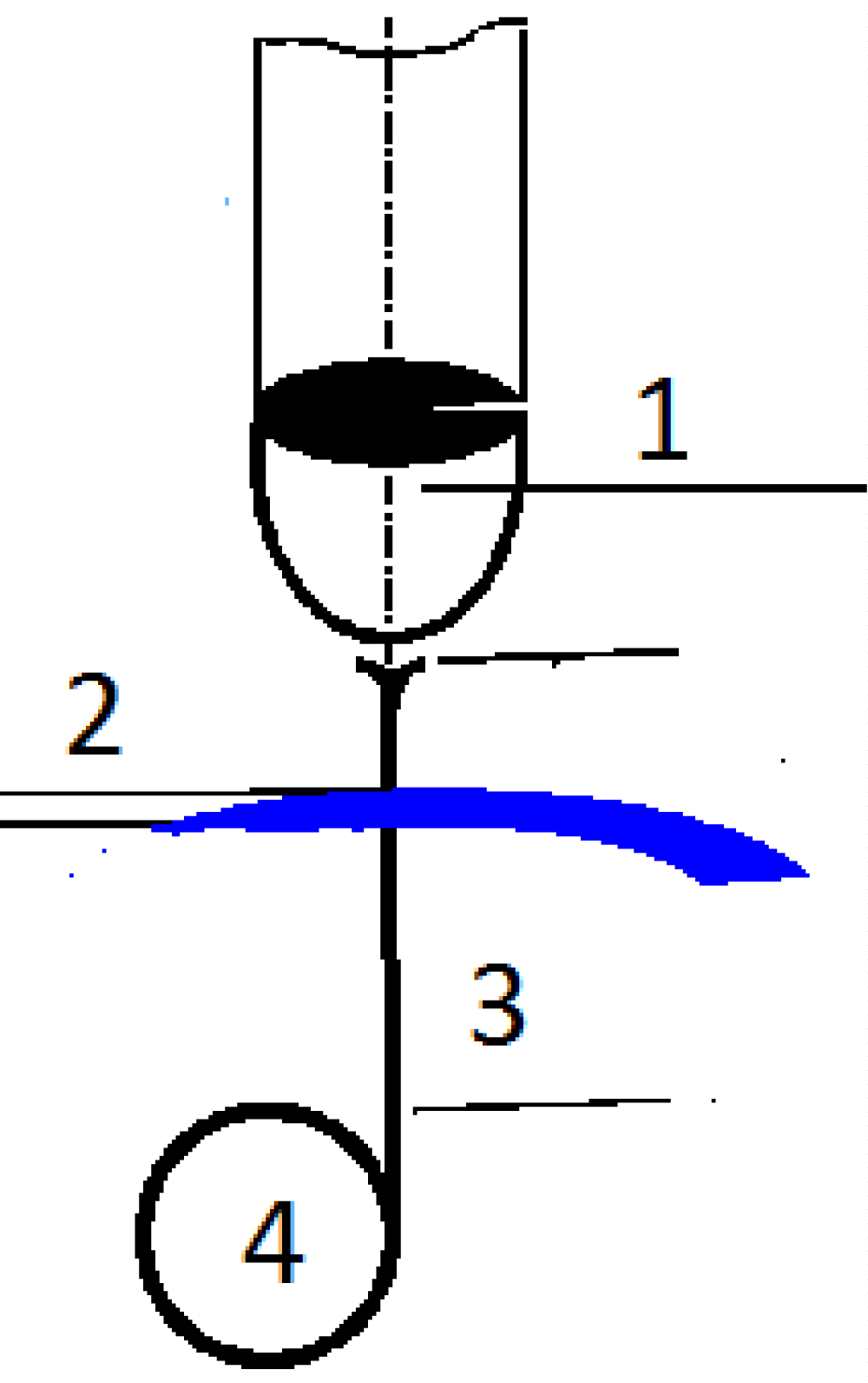
Figure 1A: Process of casting glass-coated amorphous magnetic microwires ([1-4] and below). 1. Glass tube and drop of metal, 2. Water. 3. Glass-coated microwire. 4. Rotating receiving bobbin.
Glass-coated amorphous magnetic microwire
The cast glass-coated amorphous micro- and nanowires (CGCAMNW) are manufactured by use of a rapid solidification technique, the so-called quenching and drawing procedure or modified Taylor-Ulitovsky method [1-4], as depicted in Figure 1B.
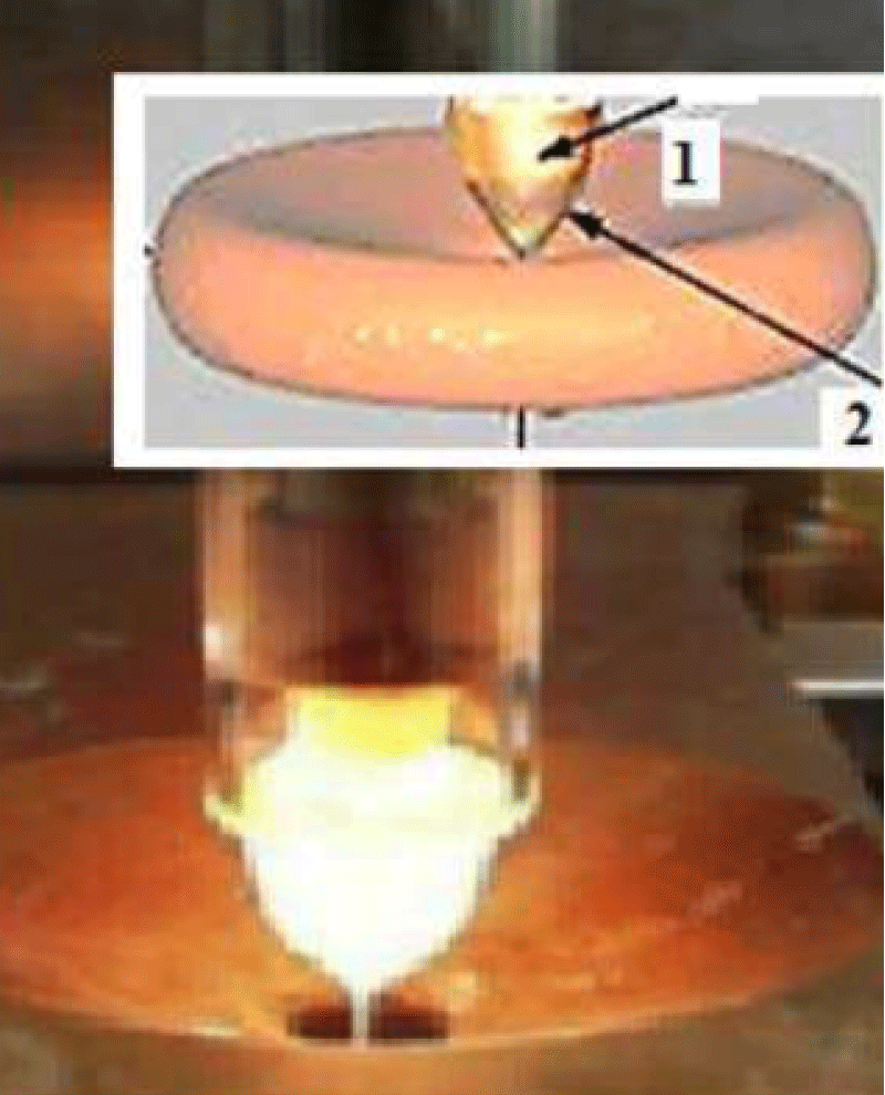
Figure 1B: Process of casting glass-coated amorphous magnetic micro-and nanowires. 1. Cylindrical zone 2. Cone zone.
In this process, an alloy in a quantity of few grams is delivered inside a glass tube held directly over suitable heating means, for example a high frequency inductor heater. The alloy is heated up to the melting point, forming a droplet. The portion of the glass tube adjacent to melting metal softens enveloping the metal droplet. A glass fiber is drawn from the softened glass portion, which is collected onto a receiving bobbin. At certain drawing conditions, molten metal can fill the glass capillary, thus, a micro wire is formed, which a metal core has covered continually by glass. The glass consumption in the process is compensated by a continuous delivery of the glass tube in the inductor zone whereas the formation of the metallic core is restricted by the initial quantity of the droplet. The microstructure of a microwire (and hence, its properties) depends considerably on the cooling rate, which can be controlled by a cooling mechanism when the metal-filled capillary enters into a stream of cooling liquid (water or oil) on its way to the receiving coil.
Micro- and nanowires
The main advantages of this method for the production of the cast glass-coated microwires are as follows [1-4]:
- The production of the continuous long pieces of a microwire up to 104 m (in the case of a drip process). For a continuous process (Figure 1C,D), the length of a microwire is not limited.
- A wide range of variations in the geometric parameters (typically the metallic core diameter Dm is in a range of 0.5 µm – 70 µm, and a glass-coating thickness is in a range of 1 µm – 50 µm).
- The control and adjustment of the geometric parameters (the inner metallic core diameter Dm and glass thickness) during production.
- The reproducibility of the physical properties and geometric parameters of the microwires in mass production.
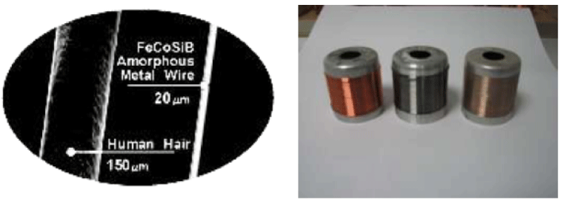
Figure 1C: Microwire can be ten times thinner than a human hair.
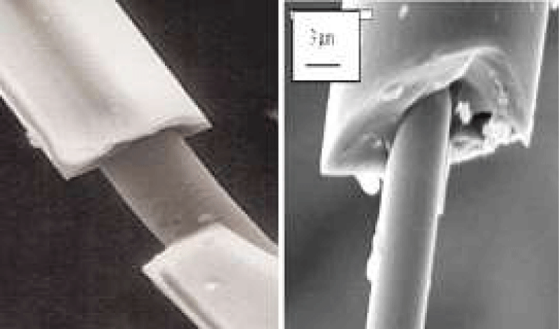
Figure 1D: Image of a glass-coated microwire showing its metallic core and the insulating shell.
The glass coating of the cast GCAMNWs, in addition to protecting the metallic nucleus from corrosion and providing electrical insulation, induces large mechanical stresses in the nucleus. Coupled with its magnetostriction, these determine its magnetoelastic anisotropy, at the origin of a unique magnetic behaviour. The residual stresses are the result of differences in the coefficients of thermal expansion of the metal and of the glass. A simple theory for the distribution of residual stresses was presented in Refs. [2-8].
The theory of residual stress is presented in Ref. [4]. We will use results of this theory. Coupled with the magnetostriction of the latter, these factors determine the magnetoelastic anisotropy which is at the origin of a unique magnetic behavior.
In cylindrical coordinates, the residual tension is characterized by the axial,σz, radial, σr, and tangential, σφ, components which are independent of the radial coordinate. The value of these stresses depends on the ratio of the radius, Rm, of the metallic kernel to the total microwire radius, Rc:
(1)
Using the cylinder–shell model, we then obtain a formula for stresses in the metallic kernel of the cast GCAMNWs:
σr = σφ ≡ Pv (2)
(3)
where P0 ~ εE1 = σo ~ 2 GPa is the maximum stress in the metallic kernel; ε is the difference between the thermal expansion of the metallic core and that of the glass shell with the expansion coefficients α1 and α2: (ε = (α1 – α2)(T* – T)); E1 is the Young modulus of the metal core, T* is the solidification temperature of the composite in the metal / glass contact region (T* ~ (800…1000) K), T is the room temperature. The technological parameter k is the ratio of Young's modulus of the glass and the metal:
k = E2/E1 ~ 0.3…0.6; ν is the Poisson ratio.
Let us consider the case where all the Poisson ratios
ν = 1/3
in order to obtain
(4)
(5)
For materials with positive magnetostriction, the orientation of the microwire magnetization is parallel to the maximal component of the stress tensor, which is directed along the axis of the microwire. Therefore, cast microwires with a positive magnetostriction show a rectangular hysteresis loop with a single large Barkhausen jump between two stable magnetization states and exhibit the phenomenon of NFMR. Equations (1-5) adequately explain the experiments concerning FMR and NFMR (see below).
We suggested a model in which the residual stresses σr and σz in the GCAMNW monotonically decrease towards the strand axis. This model differs from the models of the standard theory [2-8].
With additional longitudinal strain, which occurs when the microwire is embedded in a solid matrix that itself deforms under external influence, the following term is added to the expression for the residual axial tension:
(6)
Where Po is the force applied to the composite; Sm is the microwire cross-sectional area; k is the ratio of the Young modulus of the shell to that of the microwire; x is the ratio of the cross-sectional area of the shell to that of the microwire.
For materials with positive magnetostriction, the orientation of the microwire magnetization is parallel to the maximal component of the stress tensor, which is directed along the axis of the wire [2-8]. Therefore, cast Fe–based microwires with positive magnetostriction constant show a rectangular hysteresis loop with single large Barkhausen jump between two stable magnetization states and exhibit the phenomenon of Natural Ferromagnetic Resonance (NFMR) [2-8].
The Ferromagnetic-resonance (FMR) method is often used for investigation of amorphous magnetic materials (ribbons, wires, thin films). Both macroscopic and microscopic heterogeneity of amorphous materials can be investigated by FMR. Residual stress is an important parameter for amorphous materials which can be studied by FMR [1-3].
FMR is also used for diagnostics of the uniformity of amorphous materials. Extrinsic broadening of FMR lines due to fluctuations of the anisotropy, magnetization, and exchange-interaction constant in amorphous materials has also been investigated. Microwave experiments are very useful for investigation of spin-wave effects. In particular, microwave generation and amplification are of great interest. Investigation of structural relaxation of amorphous materials during heat treatment, using FMR is also important. Differential FMR curves combined with hysteresis curves can give important information in this case.
In the present work, cast glass-coated amorphous microwires with metallic cores and diameters between 0.5 and 25 μm are considered. The amorphous structure of the core was investigated by X-ray methods. The thickness of the glass casing varied between 1 μm and 20 μm. Using microscopy, we have chosen samples with the most ideal form, and with lengths of about 3 mm - 5 mm, for investigation. Microwires based on iron, cobalt, and nickel (doped with manganese), with additions of boron, silicon, and carbon, were studied. Microwires made from different materials have diverse magnetostriction. We have studied microwire from the same spool, whose glass casing was removed by etching in hydrofluoric acid.
In almost all cases, standard FMR spectrometers from 2 GHz to 32 GHz were used. The magnetic field was measured using a Hall sensor (with accuracy within 0.1%). In addition, magnetometer measurements determined the magnetization, needed for calculation.
The basic measurements were made in a longitudinal field configuration (external magnetic field was directed along the microwire axis). In this case, a signal of the correct form was obtained from good samples. This gives the possibility of measuring resonant-curve width.
For thick cores, skin effect must be taken into account. In this case the resonant frequency was described by the Kittel formula for a plane (with longitudinal magnetization). The g factor was estimated at two resonant frequencies as ~ 2.08 ÷ 2.1 on average. Our results are in good agreement with literature data on the g factor for amorphous materials [2-20]. In a transverse field (when the external field is perpendicular to the microwire axis), the signal was weak or not observed in samples with negative magnetostriction. Obviously, the presence of this signal is associated with non-uniformity of the high-frequency demagnetizing factor.
Natural ferromagnetic resonance
A microwire was considered to be a ferromagnetic cylinder with small radius r. For its characterization we introduce following parameters:
1. The depth of the skin layer is:
(7)
(µµo)e is the effective magnetic permeability, and Σ is the microwire electrical conductivity. In the case of our magnetic microwires, with the relative permeability |µ| near resonance of the order 102, (ω ~ (8 ÷ 10) GHz) δ changes from 1 µm to 3 µm.
2. The size of the domain wall (according to Landau-Lifshits theory) is:
Δ ~ (A/K)1/2 ~ (10 ÷ 0,1) µm, (8)
where A is the exchange constant and K is the anisotropy energy of the microwire (K~ λσ, where λ is the magnetostriction constant and σ, is the effective residual stress from the fabrication procedure [2,4] and Equations. (1-6)). The full theory gives Δf ~ 0,1 µm for the size of the domain wall of glass-coated microwires [4].
3. The radius of a single domain (according to Brown theory) is
(9)
where Ms is the saturation magnetization of microwire.
According to [2-8] the frequency of the NFMR is:
(10)
where λ is the gyromagnetic ratio. The anisotropy field is He ~ 3λσ/Ms (for exact calculations of anisotropy field, see below).
If r < δ , we have:
(11)
If r > δ, the NFMR frequency is given by (Refs. [2 - 8]):
(12)
The discovery of natural ferromagnetic resonance (NFMR) in amorphous microwires [2] was preceded by their study using standard FMR methods [4-7]. Then, the shift in the resonant field, due to core deformation of the microwire associated with fusing the glass and core at the temperature of microwire formation, was observed. The FMR line width is also of interest because it characterizes, in particular, the structural parameters [2-18].
Since the skin penetration depth of a microwave field in a metallic wire is relatively small in comparison with its diameter the resonant frequency of FMR can be determined by means of Kittel formula (Eq. (12)). Taking into account the magnetoelastic stress field [2,3], for a thin film magnetized parallel to the surface, we can obtain:
(13)
where H is the FMR field; are components of tensor of effective demagnetizing factors in case of magnetoelastic stress:
(14)
where:
Components σi (see Equations. (1-6)) are residual stresses [2,3]. Then,
(15)
Substituting the σi values obtained in our previous works [3-8] (see Equations. (1-6)), and taking into account Equations. (13), (14), we can calculate conditions for FMR:
(16)
If the glass is removed, the stress is completely removed. Then the FMR resonant field of wire without glass casing, H0, is determined from:
(17)
We have shown [1-4,6-8] that these relations quantitatively explain all of the basic features of NFMR and FMR. Note that the value of Ms required for the calculations was determined both by standard methods on a vibration magnetometer and with the use of interpolation formulas given here. The error relative to tabular values for the given alloys is not greater than 5%.
For the frequency of NFMR under the simple approximation taking εE1~ 2 GPa and k ~ 0.4 this formula can be written as:
(18)
As you can see, dependence for the frequency of NFMR (Equations. (18), and Figures 2-4) is determined from two typical values, x, ?.
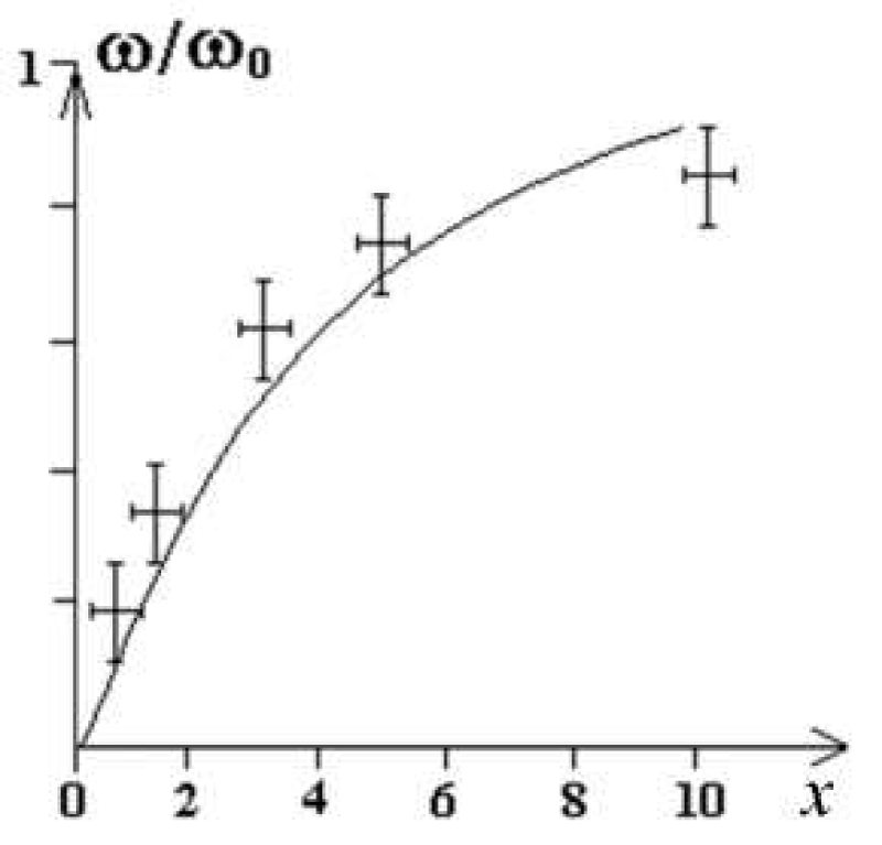
Figure 2: Theoretical curve of NFMR frequency as a function of x (according to Eqs. (18)) and experimental data [2].
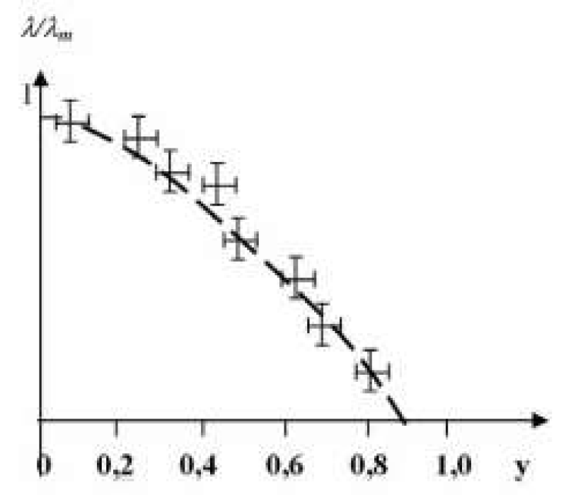
Figure 3a: Dependence of relative magnetostriction for alloy composition (Coy Fe1-y)75 (BSiC)25 series cast glass-coated amorphous magnetic microwires according to Equations. (16) – (18), where y = Co/(Co+Fe) [2].
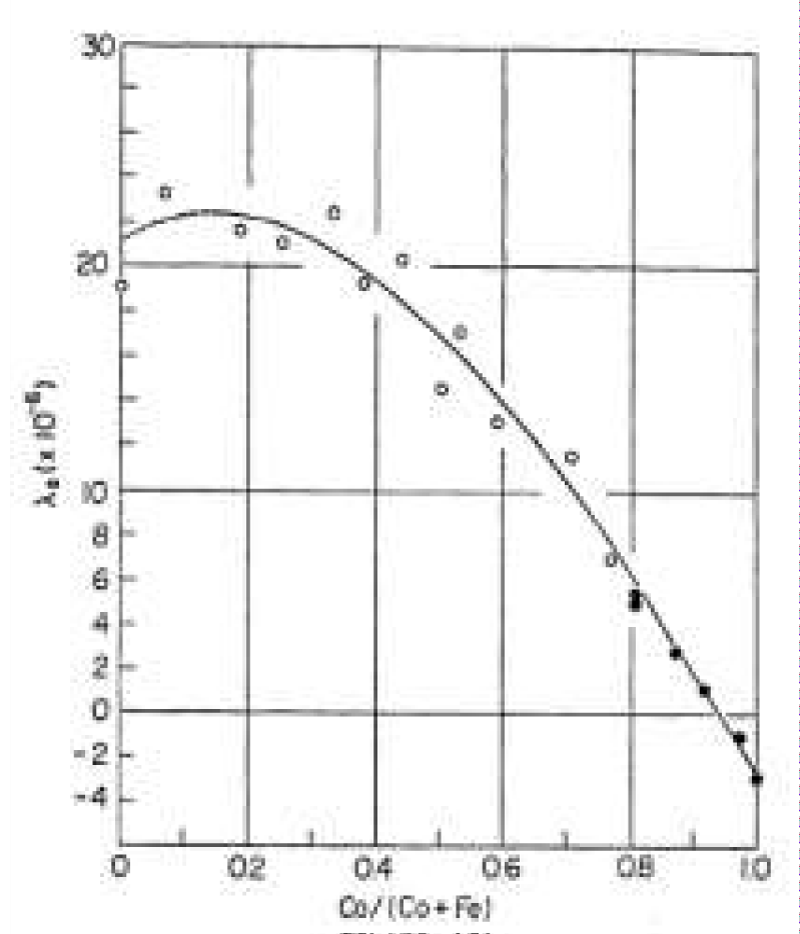
Figure 3b: Typical saturation magnetostriction λs in the amorphous Co–Fe alloys: (Fe1-yCoy)80(PC)20 ; ● (Fe1-yCoy)75(SiB)25 (according to Ref. [2]).
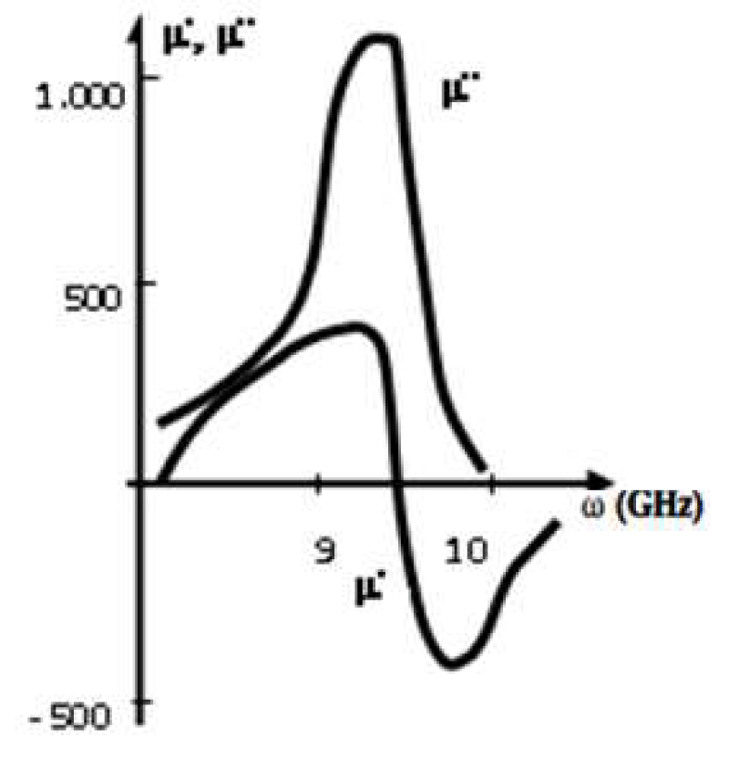
Figure 4: Frequency dispersion of the real and imaginary parts of the relative permeability around the NFMR frequency for the Fe68C4B16Si10Mn2 microwire (R3 ~ 5 μm, x ~ 5).
The basic contribution to the NFMR frequency and NFMR line width is due to the effective magnetostriction and parameter x (Equations. (18), and Figures 2-4). The residual stress in the microwire plays the dominant role in the formation of the absorption line width, as it will be shown below (Figures 5,6).
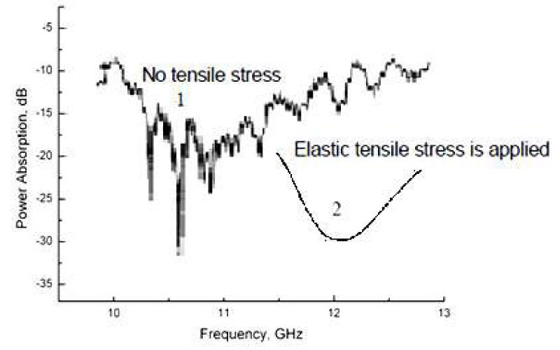
Figure 5: 1 – Average absorption characteristics of a shielding containing a microwire composite exhibiting NFMR at microwave frequencies ranging from (10…12) GHz for Fe68C4B16Si10Mn2 microwires (Rm ~ 5 μm, x ~ 5). 2 – Hypothetical absorption curve in case of an external pressure.
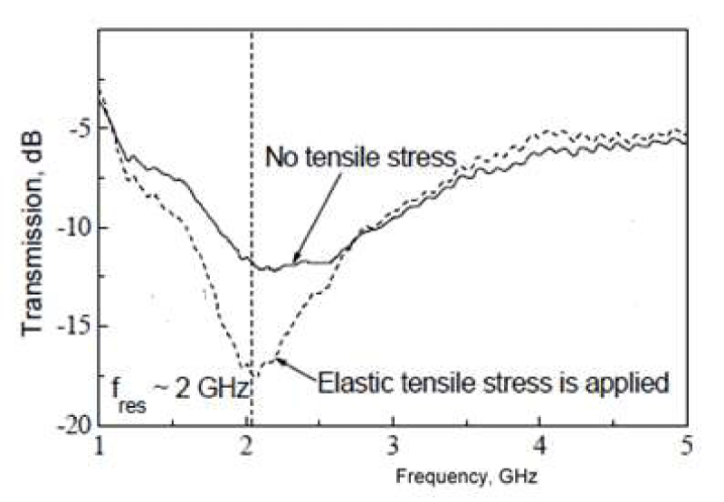
Figure 6: Stress dependence of the transmission coefficient for a single-layer composite sample measured in the free-space near field [21].
The NFMR frequency in the remote diagnostics of critical infrastructure deformations can be written as
(18a)
Where,
These formulas allow you to determine stress in the distant diagnostics of dangerous deformations of critical infrastructure objects such as bridges, dams, wind turbine towers, skyscrapers, stack-furnaces, embankments, etc. To this end, fragments of magnetic microwires will be embedded in the bulk of concrete structures or on their surface during construction or after it by means of coating with a special concrete-adhesive plaster.
When the penetration depth of the microwave field in the metallic wire is small relative to the wire diameter (on account of the skin effect), the resonant frequency in FMR and NFMR may be determined by means of Equations. (1-6). (The general theory of residual tension is presented in Refs. [2,4], but here it is enough to use the simple theory from [3]).
Substituting typical values of λ and x in Eq. (18) we reach numerical values of NFMR in a range from 1 to 12 GHz. A systematic study on the NFMR frequency for the alloy series (CoyFe100-y)75(BSiC)25 has been performed as a function of the Co content (Figure 3). The magnetostriction has then been evaluated using Eq. (18). The result is plotted in Figure 3a which shows good agreement with the magnetostriction values as determined through conventional techniques (Figure 3b.). Thus, the final theory quantitatively explains all the basic features of NFMR and FMR. However the area of experimental research in the case of small radius of a metallic nucleus radius of a microwire remains vacant.
Absorption properties
Near the NFMR frequency, the dispersion of the permeability, μ, is given by
μ(ω) = μ'(ω) + iμ''(ω) (19)
With μ'' exhibiting a peak and μ' passing through zero at resonance [4,6-8].
Figure 4 shows the resonance frequency of 9.5 GHz for a Fe68C4B16Si10Mn2 microwire.
In the vicinity of the resonance μ'' is described by [6-8]:
μ''/μdc ~ ГΩ/[(Ω – ω)² + Г²] (20)
Where μdc is the static magnetic permeability, and Г is the width of the resonant curve.
Modulating the diameter of the microwire and the magnetostriction through its composition enables one to fabricate microwires with a tailorable permeability dispersion for radio-absorption applications [6-8]:
(i) Determining the resonant frequency in the range from (9…12) GHz;
(ii) Controlling the maximum of the imaginary part of magnetic permeability.
Pieces of microwires have been embedded in planar polymeric matrices to form composite shielding for radio-absorption protection. Experiments were performed employing commercial polymeric rubber with a thickness of (1…3) mm. Microwires were spatially randomly distributed within the matrix prior to its solidification. The concentration was maintained below (8…10) g of microwire dipoles ((1…3) mm long) per 100 g of rubber [4,6-8].
A typical result obtained in an anechoic chamber is shown in Figure 5 for radio-absorbing shielding with embedded Fe68C4B16Si10Mn2 microwires. As observed, an absorption level of at least 10 dB is obtained in a frequency range of (8…12) GHz with a maximum attenuation peak of 30 dB at about 10 GHz. In general, optimal absorption is obtained for microwires with metallic kernels of diameter 2Rm ~ 10 μm (x ~ 5) and length L = (1…2) mm. These microwire pieces can be treated as dipoles whose length L is comparable to the half value of the effective wavelengths Λeff/2 of the absorbed field in the composite material (i.e., in connection to a geometric resonance). A similar result has been received for radio-absorbing shielding with a different GCAMNW [4,6-8].
It is possible to explain experimental results using the theory presented in Refs. [6-8,20]. Although the design of the absorption shielding can be based on disposing the dipolar pieces in a stochastic way, we consider, for simplicity, a theoretical analysis for a diffraction grating with a spacing between wires of Q < Λ (Λ is the wavelength of the absorbed field). The propagation of an electromagnetic wave through an absorbing shielding with microwire-based elements is characterized by transmittance, |T|, and reflectance, |Rr|, coefficients given by [6-8]:
|T| = (α2 + β2)/[(1 + α)2 + β2]; (12)
|Rr|= 1/[(1 + α)2 + β2], (13)
Where α = 2Xr/Z0, β = 2Y/Z0 with Z0 = 120π/Q, and the complex impedance Z = Xr + iY.
The absorption function, G, is correlated with the generalized high-frequency complex conductivity, Σ, (or high-frequency impedance, Z). Here we use the analogy between the case of a conductor in a waveguide and that of a diffraction grating. The absorption function, given by [6-8]:
|G| = 1 ‒ |T|2 ‒ |Rr|2 = 2α/[(1 + α)2 + β2], (14)
has a maximum of |Gm| =0.5 |G| for simultaneously α = 1 and β = 0, for which |T|2 = |Rr|2 = 0.25. The minimum |G| = 0 occurs at α = 0.
Theoretical estimations, taking into account only the active resistance of microwires, result in an attenuation within a range from (5…15) dB being much lower than the experimental results, which, for a spacing of microwires of Q = 10‒2 m, range between 18 and 15 dB, while for a spacing of Q = 10‒3 m it increases up to (20…40) dB. Thus, it becomes clear that the shielding exhibits anomalously high absorption factors, which cannot be explained solely by the resistive properties of microwires.
Let us consider the effective absorption function (as in Equation (14)):
|Geff| ~ ГeffΩeff/[(Ωeff – Ω)² + Гeff²], (15)
Where, Гeff ≥ Г and Ω ~ Ωeff = 2πc/Λ.
A microwave antenna will resonate when its length, L, satisfies the condition
L ~ Λ/[2(μeff)½]. (16)
The NFMR in a single Fe68C4B16Si10Mn2 microwire (Figure 1) occurs at Ωeff ~ 9.5 GHz, and the absorption curve in Figure 2 from Fe68C4B16Si10Mn2 microwire pieces exhibits a maximum at Ωeff ~ 10 GHz (Λ ~ 3 cm) and μeff ~ 103.
This corresponds to
L ~ 1…3 mm (17)
Where, the concentration of microwires (X2 < 0.2 according Equation (15)) is well below the percolation threshold. A higher concentration of dipoles increases both the absorption, |Geff|, and the reflectance, |Rr1|, which can be simply evaluated (Refs. [8,20]):
|Rr1| ~1 ‒ 2√ [Ω/(2πΣmm>)], (18)
Where Ω/2 ~ 1010 Hz. Equation (18) is applicable if the reflection factor, |Rr1|, is small. (We consider Σm ~1011 Hz (Ref. [8])).
It is worth mentioning also another principle of detecting mechanical strain which is examined in Ref. [20]. This principle is based on the giant magnetoimpedance (GMI) effect (Figure 3), so that it is different from that presented in Figure 6. The GMI effect demands external magnetization of the sample which is not required in the NFMR method (Refs. [6-8]).
As follows from the article, the method we proposed (method of the NFMR effect based) is more technologically advanced than the method of the GMI effect based.
Radio-absorption shielding
The designs of composites from GCAMNWs have following configurations (Figures 7-9).
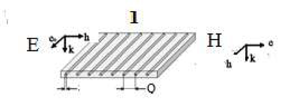
Figure 7: Composite shielding for radio absorption protection with GCAMNWs, where, were marked in microwires arranged in a diffraction grating pattern. We can consider two types of orientation of a magnetic field: E and H.
Figure 8: Diffraction grating with GCAMNWs.
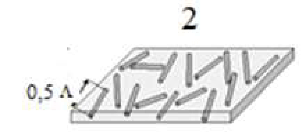
Figure 9: Composite shielding for radio absorption protection with GCAMNWs where were made in a stochastic mixture of microwires in the polymeric matrix.
Natural ferromagnetic resonance (NFMR) occurs when the sample is submitted to a microwave field without application of any biasing field other than the intrinsic anisotropy field of the microwire.
Near the natural ferromagnetic resonance frequency, ω, the dispersion of permeability μ. Given by
μ(ω) = μ' (ω) + i μ'' (ω) (2)
Exhibits a peak in μ'' and a zero crossing of μ'.
Figures 10 show resonance frequencies of 4.4; 9.0; and 9.5 GHz, and resonance widths of 1.5; 1 and 0.5 GHz. Near resonance, μ'' is expected to be described by
μ''/μdc ~ Г Ω / [ (Ω– ω)² + Г²] (3)
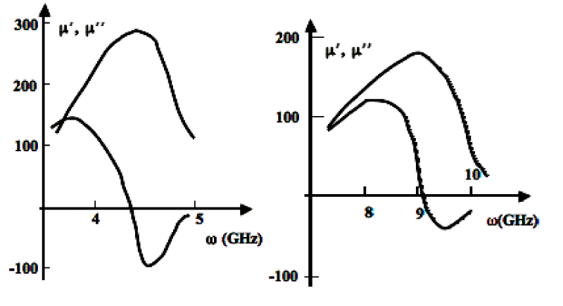
Figure 10: Real and imaginary relative permeability components around NFMR for Co59Fe15B16Si10 (a) and Fe69C5B16Si10 (b) microwires (r ~5 mm, x>8 [5-7]).
where μdc is static magnetic permeability and Г is the width of the resonant curve. Very near resonance, when Г > (Ω– ω), Eq. (3) reduces to
μ''/μdc ~ Ω / Г~ (10 ÷ 102). (4)
Monitoring the geometry of the microwire (i.e., its diameter) and the magnetostriction through its composition enables one the fabrication of microwires with tailor able permeability dispersion and for creating Radioabsorption materials:
I. Determining the resonant frequency in a range from 1 up to 12 GHz
II. Controlling the maximum of the imaginary part of magnetic permeability.
Figure 11 also shows how the frequency absorption spectrum of shielding with Fe69C5B16Si10 microwires changes when it is rotated (90º each spectrum). We attribute the changing attenuation to the lack of perfect angular distribution of microwires which length not always fit within the shielding thickness.

Figure 11: Absorption characteristics of shielding by a microwire composite with NFMR in the HF - field in the range of frequencies 10-12 GHz. Curve 1 represents an initial situation of the screen; then 2, 3, 4: the screen is turned by 90 ° about a perpendicular axis each time [1,5-7].
Theoretical estimations taking into account only the active résistance of microwires result in attenuation within the range (5 ÷ 15) dB being much lower than experimental results, which for spacing of microwires Q = 10-2 m ranges between 18 and 15 dB, while for a spacing Q = 10-3 m it increases up to 20 dB to 40 dB. Thus, it becomes clear that shielding exhibit anomalously high absorption factors, which cannot be explained solely by the resistive properties of microwires.
This corresponds to:
L ~ (1,5 ÷ 2) mm (9)
When the microwire concentration is much less than the percolation threshold. A greater concentration of dipoles increases absorption, |Geff|, but also increases reflectance, |Rr1|, which can be simply evaluated to be [1, 7]:
|Rr1| ~1 - 2√ (Ω/2π Σ3), (10)
Where Ω/2 ~1010 Hz.
The formula is applicable, and calculation of small reflectance, |Rr1| is possible, only if
Σm~1011Hz, (11)
For concentration below the percolation threshold (as Σ<2 ~ 1015 Hz).
The microwave electromagnetic response has been analyzed for a composites consisting of dipoles and diffraction grating of amorphous magnetic glass-coated microwires in a dielectric. Thys materials can be employed for radio absorbing screening. The spontaneous NFMR phenomena observed in glass-coated microwires has opened the possibility of developing novel materials with broad-band of radio absorbing materials.
The described studies provide the following basic conclusions.
(A) We have derived simple analytical expressions for residual and mechanical stresses in the metallic core of the microwire, which clearly show their dependence on the ratio of the external radius of the microwire to the radius of the metal core and on the ratio of Young's moduli of the glass and the metal. Our modeling based on the theory of thermoelastic relaxation shows that the residual stresses increase from the axis of the microwire to the surface of the microwire metallic core, which is in accordance with the previously obtained experimental data (see [2]). Therefore, in the case of glass-coated cast microwires prepared using the Taylor–Ulitovsky method, the residual stresses achieve maximum values on the surface of the metal core [2-8].
(B) Cast GCAMNWs exhibit NFMR, whose frequency depends on the composition, geometrical parameters, and deformation of the microwire. The NFMR phenomenon observed in glass-coated magnetic microwires opens up the possibility of developing new radio-absorbing materials with a wide range of properties. An important feature of cast microwires with an amorphous magnetic core is the dependence of the NFMR frequency on the deformation (stress effect). The calculations have shown (see (18), (18a)) that the shift of the NFMR frequency caused by the stress effect bc an achieve 20% before the degradation of the composite.
(C) This effect can be used for contactless diagnostics of deformations in distant objects (including critical infrastructures) reinforced by cast magnetic microwires with the stress effect of NFMR. To this end, these objects are periodically scanned with a floating-frequency radar to determine the deviation of the initial NFMR frequency due to potentially dangerous deformations of the monitored object.
(D) The overall technology of magnetic wire composites is cost-effective and is suitable for large-scale applications.
Here we have discussed the electromagnetic properties of composites with magnetic wires showing NFMR phenomena. A striking property of these materials is that the spectra of the effective electromagnetic parameters (permittivity and permeability) can be actively tuned.
Technology of glass coated amorphous and nanocrystalline microwires allows the fabrication of continuous wires.
- Taylor F. A method of drawing metallic filaments and a discussion of their properties and uses. Phys Rev. 1924;23:655. Available from: https://doi.org/10.1103/PhysRev.23.655
- Baranov SA. An engineering review about microwire. Saarbrücken (Germany): Lambert Academic Publishing; 2017. 1-42. Available from: https://ui.adsabs.harvard.edu/abs/2017eram.book.....B/abstract
- Antonenko AN, Baranov SA, Larin VS, Torcunov AV. Rapidly quenched & metastable materials. Suppl to Mater Sci Eng A. 1997;248.
- Baranov SA, Larin VS, Torcunov AV. Technology, preparation and properties of the cast glass-coated magnetic microwires. Crystals. 2017;7(6):136. Available from: https://doi.org/10.3390/cryst7060136
- Baranov SA. J Commun Technol Electron. 2003;48(2):226.
- Baranov SA. Defects-induced room temperature ferromagnetism in ZnO nanorods grown from ε-Zn(OH)₂. Tech Phys Lett. 1998;24:549. Available from: https://doi.org/10.1021/jp5058226
- Baranov SA, Yamaguchi M, Garcia KL, Vazquez M. Dimensional absorption high-frequency properties of the cast glass-coated microwires. Surf Eng Appl Electrochem. 2008;44(6):245. Available from: https://link.springer.com/article/10.3103/S106837550806001X
- Baranov SA. Engineering microwave properties of microwires. Mold J Phys Sci. 2015;14(2):201. Available from: https://ibn.idsi.md/vizualizare_articol/43550
- Marín P, Cortina D, Hernando A. High-frequency behavior of amorphous microwires and its applications. J Magn Magn Mater. 2005;290–291:1597.
- Peng H-X, Qin F, Phan M-H. Ferromagnetic microwire composites: from sensors to microwave applications. In: Ferromagnetic microwires composites: from sensors to microwave applications. Switzerland: Springer; 2016. Ch. 12–14. Available from: https://link.springer.com/book/10.1007/978-3-319-29276-2
- Qin F, Peng H-X. Ferromagnetic microwires enabled multifunctional composite materials. Prog Mater Sci. 2013;58:181–259. Available from: https://doi.org/10.1016/j.pmatsci.2012.06.001
- Kraus L, Infante G, Frait Z, Vázquez M. Ferromagnetic resonance in microwires and nanowires. Phys Rev B. 2011;83:174438. Available from: https://doi.org/10.1103/PhysRevB.83.174438
- Kraus L. Theory of ferromagnetic resonances in thin wires. Czech J Phys. 1982;32:1264–1275. Available from: https://link.springer.com/article/10.1007/BF01597425
- Reynet O, Adenot A-L, Deprot S, Acher O, Latrach M. Effect of the magnetic properties of the inclusions on the high-frequency dielectric response of diluted composites. Phys Rev B. 2002;66:094412. Available from: https://doi.org/10.1103/PhysRevB.66.094412
- Starostenko SN, Rozanov KN, Osipov AV. Microwave properties of composites with glass-coated amorphous magnetic microwires. J Magn Magn Mater. 2006;298:56–64. Available from: https://doi.org/10.1016/j.jmmm.2005.03.004
- Yıldız F, Rameev BZ, Tarapov SI, Tagirov LR, Aktaş B. High-frequency magnetoresonance absorption in amorphous magnetic microwires. J Magn Magn Mater. 2002;247:222–227. Available from: https://doi.org/10.1016/S0304-8853(02)00187-7
- Ménard D, Britel M, Ciureanu P, Yelon A. Giant magnetoimpedance in a cylindrical magnetic conductor. J Appl Phys. 1998;84:2805–2811. Available from: https://doi.org/10.1063/1.368421
- Ménard D, Yelon A. Theory of longitudinal magnetoimpedance in wires. J Appl Phys. 2000;88:379–384. Available from: https://doi.org/10.1063/1.373671
- Adar E, Yosher AM, Baranov SA. Natural ferromagnetic resonance in cast microwires and its application to the safety control of infrastructures. J Phys Res Appl. 2020;3:118–122. Available from: https://doi.org/10.29328/journal.ijpra.1001028
- Makhnovskiy D, Zhukov A, Zhukova V, Gonzalez J. Tunable and self-sensing microwave composite materials incorporating ferromagnetic microwires. Adv Sci Technol. 2008;54:201–206. Available from: http://dx.doi.org/10.4028/www.scientific.net/AST.54.201